
Get in touch with TIME Company

DKO-ADAP
Hydraulic Gauge Port Adapters — IKIN by TIME Hydraulic
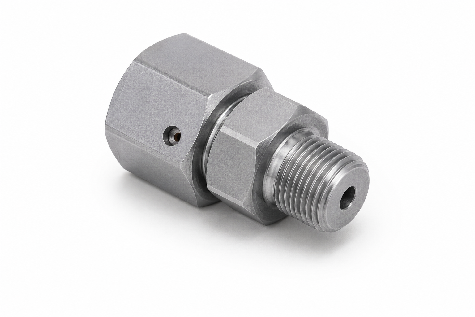
Choose a straight or 90-degree DKO hydraulic gauge port adapter by defining both sides of the connection: the tube-fitting interface already on the machine and the test point, hose, sensor, or pressure gauge being added. TIME Hydraulic reviews the connection geometry, quantity, fluid, pressure requirement, and access envelope before assigning a part.
- Engineer-reviewed quote within one business day
- Prototype parts ship in 3 working days after drawing approval
- 100% inspection before packing
- Part number, drawing, or measured photograph accepted
Your drawings and specifications are treated as confidential and are not shared outside the people quoting and making your part.
Gauge Port Adapters and Test Point Fittings at a Glance
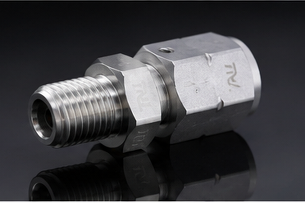
A hydraulic gauge port adapter brings diagnostic access to an existing hydraulic connection without making the gauge thread the machine-side standard. The DKO end seals at a metric 24-degree cone and O-ring face; the diagnostic branch is a separate interface, so both ends belong on the same drawing.
Published product forms
TP straight, 90-degree elbow, bulkhead BH, 24-degree male cone DKO, and stud-end variants
Diagnostic interface
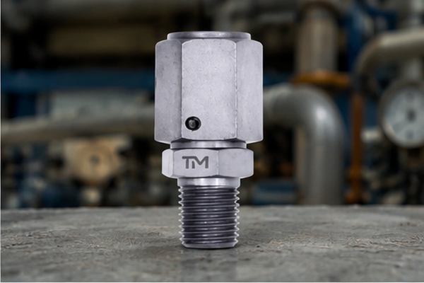
M16 x 2 where the selected design uses the ISO 15171-2 connection end
Trial order
Starts from 100 pieces, with your own logo included
Sample dispatch
Normally 3 working days; charging depends on the item
Production schedule
10–30 working days, confirmed with the quotation
Quality warranty
3-year quality warranty
The first drawing decision
Record the line-side end and the diagnostic-side end as two separate specifications. That one discipline prevents the common mistake of ordering the right M16 x 2 test connection on the wrong DKO tube series, or the right DKO end with the wrong gauge connection.
Start Trial OrderTest Port and Thread Families We Cover
A hydraulic test port gives repeatable access for pressure measurement, but the name alone does not identify complete device geometry or features. A useful RFQ states the existing connection, the diagnostic route to be added, and the direction in which the gauge or hose must leave the line.
Sealing Forms, Materials and Corrosion Protection
Material selection follows only after the fluid, temperature, environment, pressure duty, and mating components are known. Carbon steel, stainless steel, and seal-compound names are broad categories; actual service suitability depends on the adapter specification and the complete operating conditions.
Three sealing mechanisms to keep separate
Cone and O-Ring
The DKO O-ring seals at the 24-degree cone face while the swivel thread generates clamping load. Inspect the cone and O-ring land rather than applying pipe-thread sealant to a non-thread-sealing connection.
Face or Shoulder O-Ring
ORFS and O-ring boss connections place the elastomer at a flat face or port counterbore. The thread may look familiar while the sealing surface and groove geometry are entirely different.
Tapered Thread
NPT-family connections develop their seal through tapered thread engagement and the specified sealing practice. A straight hydraulic thread that starts into the port is not a substitute.
Material and fluid review at quotation
Hydraulic fluid
PG. 01
Why it changes the selection
Mineral oil, water-glycol, biodegradable fluids, fuels, and process liquids expose seals and metals differently.
What to send
Fluid trade name, base type, and concentration where relevant.
Temperature
PG. 02
Why it changes the selection
Elastomer behavior, viscosity, corrosion rate, and metal expansion change across the service range.
What to send
Minimum, continuous, and short-duration maximum.
Environment
PG. 03
Why it changes the selection
Outdoor salt, washdown, chemicals, mine dust, and indoor mobile service create different corrosion and cap requirements.
What to send
Location, contaminants, cleaning method, and desired service interval.
Mating material
PG. 04
Why it changes the selection
Hardness, coating, and galvanic pairing affect thread damage and corrosion at the connection.
What to send
Existing fitting or port material and surface condition.
Seal service
PG. 05
Why it changes the selection
Static sealing and repeated diagnostic connection place different demands on the O-ring and valve.
What to send
Connection frequency, dwell time, and any leakage limit.
Important Note
PG. 06
Do not select an O-ring by temperature alone
NBR and FKM labels describe material families, not guaranteed service in every fluid or duty cycle. Send the fluid and temperature together so the quoted seal can be reviewed against the complete application.
Thread, Pressure and Temperature Specifications
This is an abbreviated list of connection families and the standards that define their geometry. Pressure, proof pressure, connection-under-pressure capability, and temperature are product-level data for the selected TIME adapter and quotation; a thread name alone does not establish them.
M16 x 2
24° DKO
37° JIC
0° ORFS
55° BSPP
60° NPT
30° JIS
90° O-ring
Diagnostic test coupling
M16 x 2
Reference
ISO 15171-2:2016
Decision Boundary
Defines the diagnostic connection end; application conditions still control product use
DKO O-ring seal cone
24°
Reference
ISO 8434-1:2018
Decision Boundary
Identifies the connector family, not a TIME rating
JIC flare
37°
Reference
SAE J514 family
Decision Boundary
Seat angle and thread both need confirmation
ORFS
Flat face, 0° reference plane
Reference
ISO 8434-3:2005 family
Decision Boundary
O-ring groove and face condition matter beyond thread size
BSPP
55° thread form
Reference
ISO 228-1 family
Decision Boundary
Parallel thread does not identify the final seal arrangement
NPT
60° thread, 1:16 taper
Reference
ASME B1.20.1-2013 (R2018)
Decision Boundary
Dimensional conformity does not establish adapter working pressure
JIS flare
30°
Reference
JIS B8363 family
Decision Boundary
Some related forms use BSPP threads; the seat still differs from JIC
SAE straight-thread O-ring port
O-ring at 90° port face
Reference
SAE J1926/1_202301
Decision Boundary
New-design guidance favors ISO 6149; installed ports must still be identified directly
Why the table stops at interface facts
ISO 8434-1 states that its pressure values are not guaranteed minima, and ISO 19879 treats performance evaluation as a separate testing activity. The quoted adapter therefore needs model-level pressure, fluid, temperature, seal, and acceptance criteria before release.
Request a Model-Specific DrawingPricing, Lead Times and Order Terms
Cost is driven by connection geometry, material, seal, quantity, inspection scope, marking, and packing rather than a single price for a “part type.” Send an accurate drawing or measured record of the existing connection with the required quantity, so the quotation can resolve both fit and commercial terms.
SPEC.01
What moves the quotation
| Driver | Effect on the order | How to keep it controlled |
|---|---|---|
| Standard versus custom ends | Custom thread, cone, branch, or wrench geometry adds drawing and production work | Send the mating drawing or a traceable sample before the quote |
| Straight versus 90° body | Elbow orientation and clearance can change tooling and inspection points | Dimension the clocking and no-go envelope |
| Material and seal | Fluid, temperature, corrosion exposure, and availability change the selected construction | State the complete duty rather than naming a preferred material alone |
| Quantity and logo | Setup and marking cost is distributed across the batch | Give trial, annual, and call-off quantities where available |
| Inspection documents | Additional acceptance records need to be scoped before production | List every document and acceptance criterion in the RFQ |
TERMS.03
Inspection, Traceability and Warranty
We run 100% inspection before packing — every piece rather than a sample drawn. Material traceability is held through production, and the product family has passed fatigue testing.
Order controls
SYS.CTRLConnection review
The drawing separates line-side geometry, diagnostic-side geometry, seal, series, orientation, and application inputs.
Production traceability
Material identity is carried through the manufacturing record for the order.
Finished-part inspection
Every piece is inspected before packing against the order definition.
Document release
We hold current ISO and SGS certificates, and they go out with the quotation.
3-Year Quality Warranty
Products carry a 3-year quality warranty.
100% Finished-Part Inspection
Every piece is inspected before packing rather than relying on a sampled lot alone.
Drawing-Controlled Release
Acceptance is tied to the agreed part definition, so the connection family and the selected product rating remain separate decisions.
Put qualification requirements into the purchase specification
If the application needs a model-specific proof, leakage, cyclic, coating, material, or fluid-compatibility record, name it before the drawing is approved. A standard thread designation and a company certificate do not replace the product-level acceptance criteria on the order.
How to Order: From Part Number to Delivery
Order Process
STEP 01: REFERENCESend whatever reference is available—a stamped part number, a controlled drawing, or a clear photograph with a ruler beside the connection.
STEP 02: IDENTIFICATIONDescribe both sides separately: the DKO or port end and the pressure gauge, test hose, sensor, or M16 x 2 diagnostic end.
STEP 03: APPLICATION DUTYAdd the duty, including fluid, required pressure, pressure spikes, temperature range, environment, and connection frequency.
STEP 04: INSTALLATIONRecord access constraints: straight or 90-degree preference, wrench clearance, hose route, and nearby obstructions.
STEP 05: REVIEW & APPROVALApprove the drawing after TIME returns an engineer-reviewed quotation and resolves open fit questions.
STEP 06: QUALITY & DISPATCHRelease shipment only after inspection against the order definition and confirmation of dispatch terms.
A usable cross-reference package
Best case: controlled drawing
Show the complete adapter, both mating ends, thread callouts, tube OD and series, sealing faces, straight or 90-degree orientation, material and seal requirement, and every acceptance dimension. Add the machine or assembly reference so the engineering review can distinguish a production replacement from a new installation.
Workable case: old part and measurements
Photograph the whole part and each end square to the camera, include a ruler or caliper reading, and record pitch with a gauge. Add the equipment make and model as context, but do not use the machine name as a substitute for measuring the actual connection.
Measurement record for an unidentified end
How to capture it
Caliper reading across the male thread or inside the first full female thread.
Why it matters
Narrows the nominal size without relying on appearance.
How to capture it
Metric pitch gauge or threads-per-inch gauge against a backlight.
Why it matters
Separates look-alike metric, BSP, and UN families.
How to capture it
Compare diameter at two points along the thread.
Why it matters
Separates parallel connections from pipe-thread interference seals.
How to capture it
Photograph and measure the cone or flat face.
Why it matters
Distinguishes 24°, 30°, 37°, flat-face, and port O-ring forms.
How to capture it
Record tube OD and any L/S marking for DKO.
Why it matters
Prevents a same-thread, wrong-series selection.
How to capture it
Show both mating ends and the desired hose or gauge direction.
Why it matters
Prevents swapping the machine side and the measuring side.
Where These Test Point Fittings Are Used
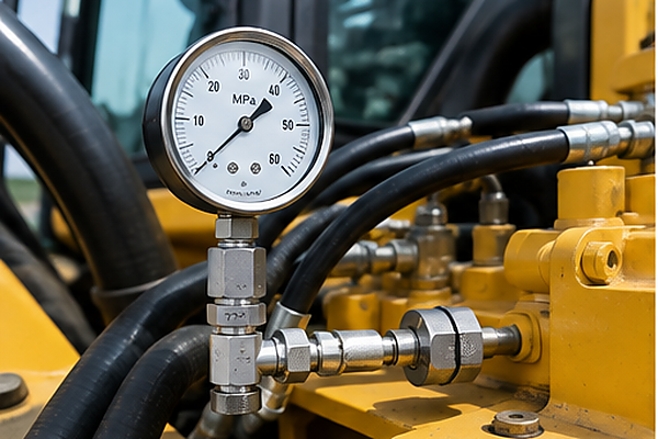
Hydraulic gauge port adapters provide temporary access for pressure tests, repeatable condition checks, commissioning, troubleshooting, and permanent sensor access when the full connection is engineered for the job. Common locations include pumps, valves, cylinders, manifolds, test hoses, mobile machinery, construction equipment, and industrial hydraulic systems.
01
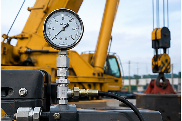
Mobile Equipment Service
Route a hose or pressure gauge away from guards and crowded valve blocks, then confirm the correct diagnostic coupling for the machine. See the excavator hydraulic test point application.
02
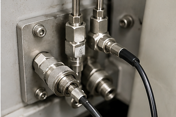
Crane Diagnostics
Define pressure-measurement access around load-holding circuits, limited wrench space, and scheduled inspection routes. Review the crane hydraulic test fittings application.
03
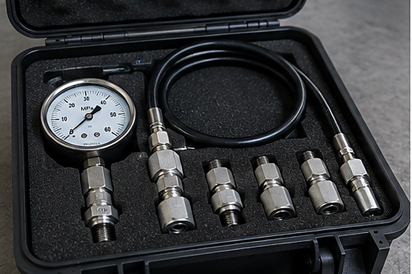
OEM and Retrofit Lines
Add an accessible test point without treating a convenient thread as proof of fit. The hydraulic test hoses and fittings hub shows the wider diagnostic chain.
04
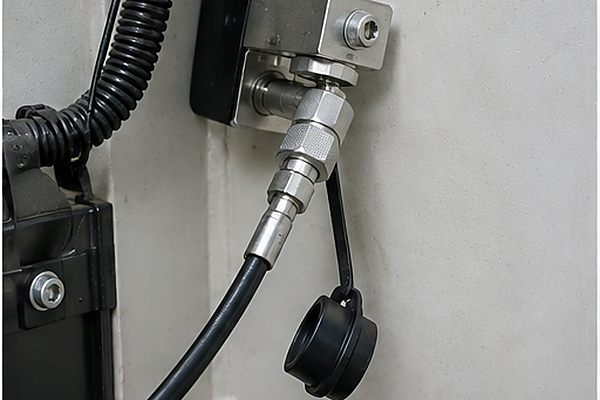
Portable Gauge Kits
Standardize the gauge-side or hose-side interface while keeping machine adapters labeled by family. This reduces field improvisation without claiming universal compatibility.
05
Permanent Sensor Access
Use a branch or bulkhead route where an instrument needs a stable mounting position. Gauge mass, vibration, impulse behavior, and service access belong in the application review.
06
Test Hose Assemblies
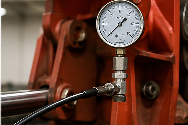
Match the adapter to the hose end and test point as one system. Compare related test hose end fittings when a remote gauge is preferable to direct mounting.
Manufacturing and supply record
TIME Hydraulic began in 2009, moved into its own development work in 2014 through wind-power applications, and built its Changzhou plant in 2017 on a 5,000 square metre site. Companies we have supplied include SANY, XCMG, Zoomlion, CRRC, Hengli, Caterpillar, Parker, HAWE, Bucher and Argorhytos.
Diagnostic Adapter Engineering Tools
Adapter RFQ Readiness Checklist
Verify your Request for Quote inputs, including line-side geometry, seal type, and series prior to submission.
Access ToolDKO Interface Definition Builder
Define the exact metric 24-degree cone interface specifications for your diagnostic measuring side.
Access ToolGauge Test Point Connection Checker
Verify the compatibility between your direct pressure gauge instruments and standard machine-side test points.
Access ToolStraight vs 90-Degree Access Selector
Evaluate installation clearance and wrench access to determine whether a straight body or 90-degree elbow is required.
Access Tool
Knowledge Base
Hydraulic Gauge Port Adapter FAQs
What is a hydraulic gauge port adapter?
It adds a pressure-gauge, sensor, test-hose, or diagnostic connection to an existing hydraulic port or tube connection. The adapter must define the line-side seal and the measuring-side connection separately.
What is a hydraulic test point?
A hydraulic test point is a normally closed diagnostic coupling that opens when the mating probe or hose is connected. ISO 15171-2:2016 covers an M16 x 2 diagnostic interface used for this purpose.
Is a DKO fitting the same as a test point?
No. DKO describes a metric 24-degree cone and O-ring sealing form within the ISO 8434-1 family; a test point is a separate diagnostic connection that may be incorporated into a DKO adapter.
Are MINIMESS, Test 20, and M16 x 2 interchangeable terms?
They are related, but not universal synonyms. MINIMESS and Test 20 are commercial family names, while M16 x 2 identifies a standardized connection end; model-level valve, rating, material, and mating details still need confirmation.
What measurements identify a DKO connection?
Record the metric thread diameter and pitch, tube outside diameter, light or heavy series, 24-degree cone condition, O-ring position, and male or female end. A close photograph with a ruler and the opposite mating part reduces ambiguity.
Should I choose a straight or 90-degree gauge port adapter?
Choose straight where axial space, wrench swing, gauge mass, and hose routing are clear. Choose 90 degrees when the diagnostic branch needs to turn away from guards or adjacent fittings, and define elbow orientation on the drawing.
Can a metric thread screw into a BSPP port?
Some near-size combinations may start, but partial engagement is not proof of a safe connection. Identify taper, pitch, diameter, seat, and seal before assembly; DGUV has documented dangerous metric/inch mix-ups.
How do I connect a pressure gauge without mounting it directly on the line?
Use a correctly rated test point and microbore test hose, then connect the gauge at a supported location. Match the gauge thread and the diagnostic coupling independently, and follow the machine procedure for live testing.
What pressure and temperature can the adapter handle?
The answer belongs to the selected TIME model, size, material, seal, fluid, and duty cycle; a thread standard alone cannot supply it. Send the maximum system pressure, spikes, minimum and maximum temperature, fluid, and desired connection behavior for the quotation.
How quickly can TIME quote and ship prototypes?
Engineer-reviewed quotations are returned within one business day. Prototype parts ship in 3 working days after drawing approval.
What is the minimum order and sample policy?
Trial orders start from 100 pieces, with your own logo included.
