Get in touch with TIME Company


Hydraulic test hoses, diagnostic couplings, adapters, and gauge connections
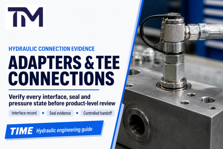
The Hydraulic Test Connection Thread Guide is a practical fit-check process for matching the full connection chain: the system port, male or female side, size, pitch, straight or tapered form, sealing surface, pressure rating, hose bore, and instrument interface.
That chain matters because a fitting can screw in and still be wrong. A match can fail at the O-ring face, cone seat, flare, tapered pipe interface, gauge connector, or pressure boundary. For fluid power systems, the correct answer is a fit decision, not just a diameter lookup.
What a Hydraulic Test Connection Thread Must Prove
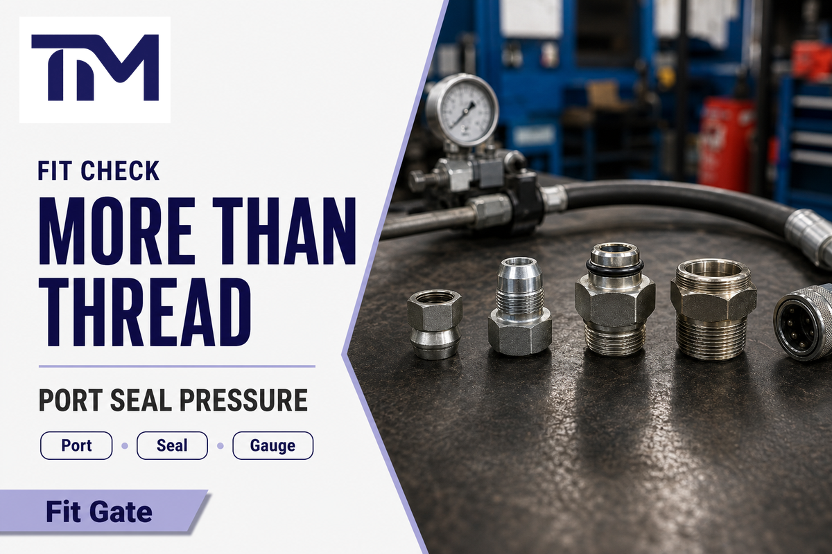
Before a test connection is approved, it must prove more than mechanical engagement. Confirm the port standard, form, sealing face, pressure class, test hose end, and gauge, sensor, or data recorder interface. If one part in that chain is guessed, the connection may leak, read incorrectly, or be unsafe.
Use port identity as one field in the specification. In a complete RFQ, write something like “male M16 x 2 diagnostic coupling for ISO 15171-2 context, DN2 hose, gauge-side adapter required,” not only “M16.”
Key takeaway
Connection name tells you how parts engage; the port, leak boundary, pressure rating, fluid, hose bore, and instrument side tell you whether the test connection is fit for service.
Start With the System Port, Not the Hose End
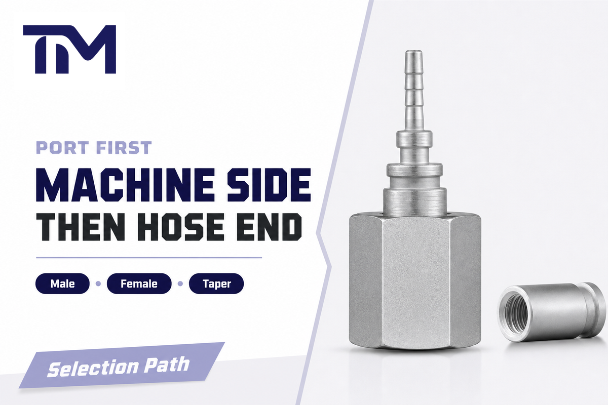
Start with the installed port because it controls the selection path. Identify the machine-side port first, then match the hose end or adapter to it. This keeps the user from forcing a convenient test hose onto the wrong port family, especially when old equipment, imported machines, or mixed fitting stock are involved.
Record whether the port is male or female, internal thread or external thread, straight thread or tapered thread. Then identify the sealing method. In fluid power work, the leak boundary may be made by tapered interference, an O-ring, a cone seat, a flare, or a bonded washer, depending on the connection type.
Identify Thread Diameter, Pitch, and Taper
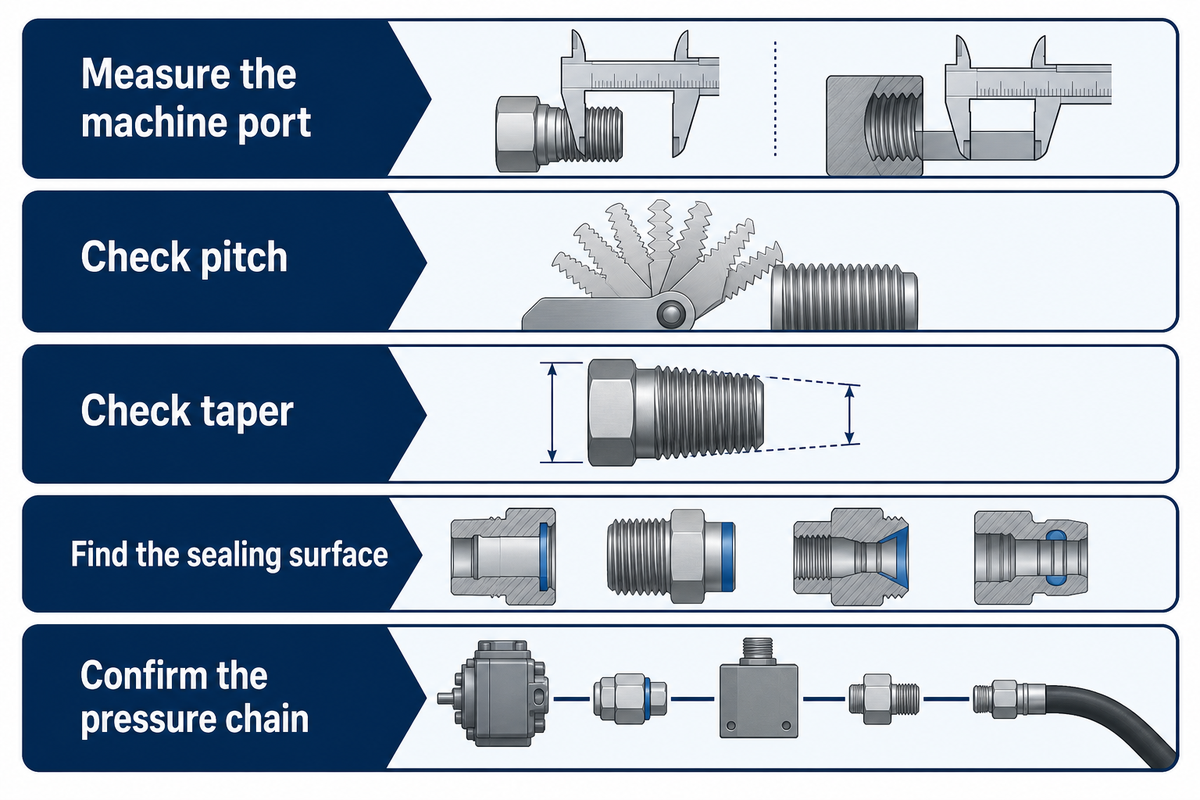
Connection identification should confirm diameter, pitch, and form before a fitting is selected. For the male side, measure the outside diameter. For the female side, measure the inside diameter. Then use a pitch gauge for pitch, threads per inch, or metric threads.
- Measure the machine port – capture male or female side and outside or inside diameter.
- Check pitch – record metric pitch or threads per inch with a thread pitch gauge.
- Check taper – compare diameter near the end and farther back to see whether the form is tapered or parallel.
- Find the sealing surface – identify threaded interface, O-ring, cone seat, flare, or face contact.
- Confirm the pressure chain – compare port, adapter, hose, gauge, and coupling ratings.
As a thread identification guide, this article helps a buyer identify hydraulic fitting type from measured data, not from shape alone. Treat each mechanical connection as part of fluid port and connector identification: thread engagement positions the parts, and the correct seat creates a leak-resistant connection. If the machine uses a hydraulic coupler, confirm the same connection type on the instrument side.
Do not use a single photo as the final evidence. Similar-looking fitting ports can have different pitch, angle, or sealing surfaces. Use the photo for supplier screening, but let measured data control the quote.
Match the Seal: Cone Seat, O-Ring, Flare, or Tapered Pipe
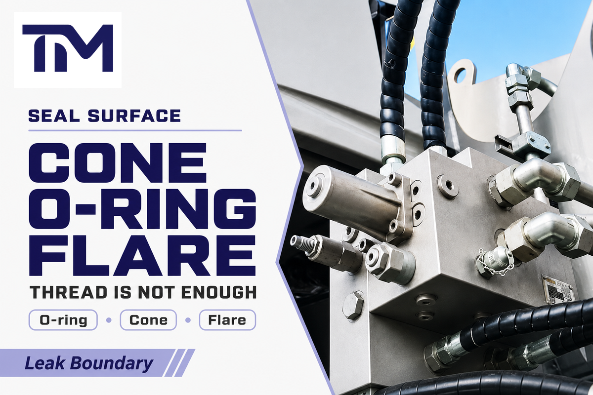
Leak prevention depends on where the connection closes. Straight thread designs may use an O-ring or washer. JIC is tied to a flare face. NPT and NPTF are tapered pipe-thread families, but their sealing behavior is not identical; follow the port standard and supplier instructions before adding sealant. Cone-seat test hose fittings close at the cone, not by thread friction alone.
This is why “the part fits” is not the same as “the fitting closes.” The interface style must match the port design and pressure service.
Do
- Measure diameter and pitch before ordering.
- State the leak surface in the RFQ.
- Ask for supplier confirmation when the fluid, pressure, or port standard is unclear.
Don’t
- Assume a near-fit part is safe.
- Use tape to compensate for a wrong interface design.
- Mix BSP, NPT, JIC, and metric names without a measured check.
Thread-Port-Seal Fit Matrix
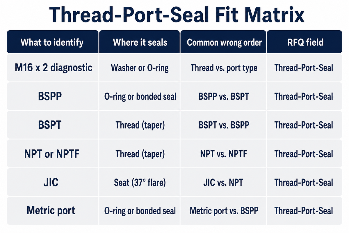
Use this matrix as a procurement and QA worksheet. It does not replace the machine drawing or supplier drawing, but it forces the buyer to separate connection identity from the leak surface and pressure boundary.
| Family | What to identify | Where it seals | Common wrong order | RFQ field |
|---|---|---|---|---|
| M16 x 2 diagnostic | Confirm ISO 15171-2 scope, coupling side, and stud end | Diagnostic coupling design | Calling every test point M16 x 2 | M16 x 2, ISO scope, pressure, fluid |
| BSPP | Parallel form and sealing washer or O-ring detail | Washer, O-ring, or face depending on design | Treating BSPP like tapered pipe | BSPP size, seal type, male or female |
| BSPT | Tapered form and thread engagement | Thread interface with compatible sealing practice | Mixing with NPT because both are tapered | BSPT size and service fluid |
| NPT or NPTF | National pipe thread family and taper | Thread interference, with compatible sealant practice when specified | Using it where a face or cone seal is required | NPT/NPTF, size, sealant rule |
| JIC | Thread size plus 37 degree flare interface | Metal flare contact | Treating JIC as NPT by nominal size | JIC 37 degree flare, size, side |
| Metric port | Diameter, pitch, straight or tapered form | O-ring, cone, or washer depending on port design | Ordering by diameter but omitting pitch | Metric size, pitch, seal style |
Where M16 x 2 and ISO 15171-2 Fit in Test Point Connections
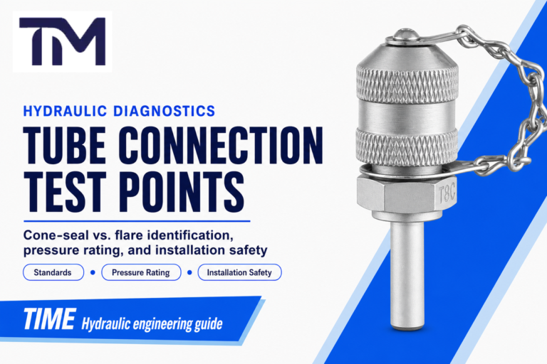
For selection support, review hydraulic test point connection options when the specified connection family matches the drawing and operating conditions.
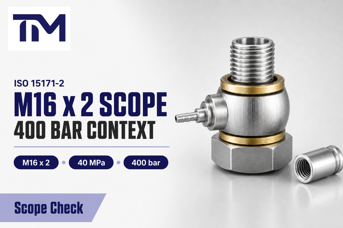
M16 x 2 is important in diagnostic couplings, but it is not a universal rule for every test connection. ISO 15171-2:2016 is scoped to diagnostic couplings with an M16 x 2 connection end for connection under pressure, and the ISO page should be checked for its current lifecycle status before formal compliance language is used.
“Coupling with M16 x 2 end for connection under pressure.”
ISO 15171-2:2016 public title scope
M16 x 2 Diagnostic Scope Box
- ISO 15171-2:2016 title scope: hydraulic diagnostic couplings with M16 x 2 end for connection under pressure.
- ISO’s official page lists the 2016 edition as Published and under systematic review, with last confirmation shown in 2021.
- The public abstract names four stud-end standards in this scope: ISO 6149-2 M14 x 1.5, ISO 9974-2 M14 x 1.5, ISO 1179-2 G 1/4, and ISO 11926-2 7/16-20 UNF.
- Connection-under-pressure limit in the public abstract is 40 MPa, or 400 bar.
- That page gives a maximum working pressure context of 63 MPa, or 630 bar, with material, design, working conditions, and application caveats.
- Mineral-oil hydraulic systems are the stated scope; other fluids require supplier and purchaser agreement.
Keep the numbers separated in the RFQ: 40 MPa, 400 bar, and 5,802 psi describe the ISO public connection-under-pressure context without tools, not the working-pressure ceiling. The 63 MPa, 630 bar, and 9,137 psi values describe maximum working pressure context for the coupling, not a guarantee for every finished assembly. For DN2 and DN4, ask the supplier to confirm the live drawing before writing 2 mm or 4 mm into the RFQ; do not infer dimensions from the DN name alone. Background fitting pages list 60° for NPT, 55° for BSP, and 37° for JIC flare context.
For a buyer, that means M16 x 2 should trigger more questions, not fewer. Ask whether the order needs ISO 15171-2 diagnostic coupling language, which of the four stud-end standards is involved, whether the fluid is mineral oil, and whether connection under pressure is actually part of the service case. Ports outside those standards need adapter review or a different coupling type, not a universal M16 x 2 assumption.
BSPP, BSPT, NPTF, Metric, and JIC: What to Check Before Ordering
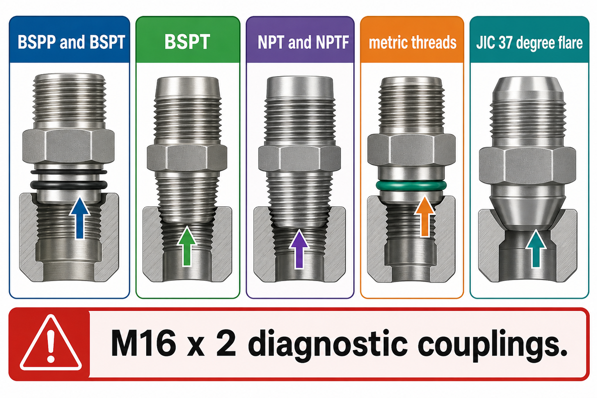
Fittings can use several connection families. Some are common in general fluid power systems, some are tied to specific machine regions, and some are used on test-point accessories or gauge adapters. Ask “Which family, interface, and pressure class does this port require?” before asking which connection hydraulic fittings use in general.
JIC and NPT are not the same. JIC is tied to a flare sealing interface, while NPT and NPTF are tapered pipe-thread families. BSPP, BSPT, metric threads, and M16 x 2 diagnostic couplings also need separate checks. The safest RFQ names the family and the sealing method together.
In connection vocabulary, British Standard Pipe covers BSPP and BSPT, ISO metric screw thread language can appear on metric ports, and Unified Thread Standard terms may appear around UNF instrument or stud-end references. SAE International standards and JIC fitting terminology belong in the same note only when the flare interface is truly part of the connection. ORFS is a separate O-ring face family, while “screw thread” and “piping and plumbing fitting” are broad words that still need pressure and interface checks.
Pressure Chain Safety Map
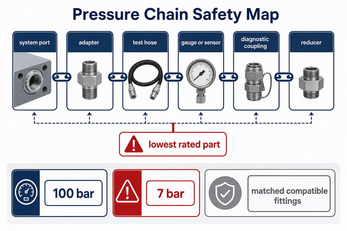
Pressure rating is a chain, not a sticker on one part. Check the system port, adapter, test hose, gauge or sensor, diagnostic coupling, and any reducer. Treat the lowest rated part as a ceiling, then review material, design, working conditions, fluid, application, compatible fittings, and high pressure testing.
| Reference check | What it prevents | Buyer action / source basis |
|---|---|---|
| Working pressure | Running a hose, adapter, or gauge beyond its intended service boundary | Ask for the rating of every component in the test chain |
| Connect-under-pressure limit | Confusing connection capability with full operating approval | State whether the test point will be connected while pressurized |
| ISO connection context | Treating 40 MPa / 400 bar connection-under-pressure wording as approval for every assembly | Separate ISO 15171-2 connection context from the finished hose rating |
| Maximum working-pressure context | Turning 63 MPa / 630 bar / 9,137 psi context into an unverified blanket guarantee | Request the live supplier datasheet for the exact coupling, hose, gauge, and adapter |
| Fluid and seal material | Using a seal material outside its fluid scope | Name mineral oil or the exact alternative fluid in the RFQ |
| Matched compatible fittings | Substituting a near-fit adapter in a pressurized system | Request drawing review and treat replacement verification as pressure-test work |
| Stored energy and injection risk | Treating a leak as only a cleanliness or downtime problem | Treat HSE’s 100 bar and 7 bar injury examples as a safety-floor warning, not a safe threshold |
| Microbore hose name | Assuming DN2 or DN4 automatically proves 2 mm or 4 mm for the purchased hose | Use the DN name as a selection clue, then confirm the live drawing |
HSE Safety Boundary for Pressurized Hydraulic Work
HSE warns that hydraulic injection injury can occur from pressurized fluid, with serious reported cases over 100 bar and anecdotal evidence as low as 7 bar. When replacement or maintenance occurs on a pressurized system, fittings should be matched and compatible with the original equipment manufacturer’s specification, and verification should be treated as pressure-test work.
Do not present burst pressure as a normal operating target. Proof or test pressure, burst pressure, working pressure, and connection-under-pressure capability answer different questions. If a supplier cannot confirm the pressure chain, the buyer should not approve a substitute connection for a pressurized machine.
Test Hose and Instrument Fit: Gauge, Sensor, Data Recorder, or Test Kit
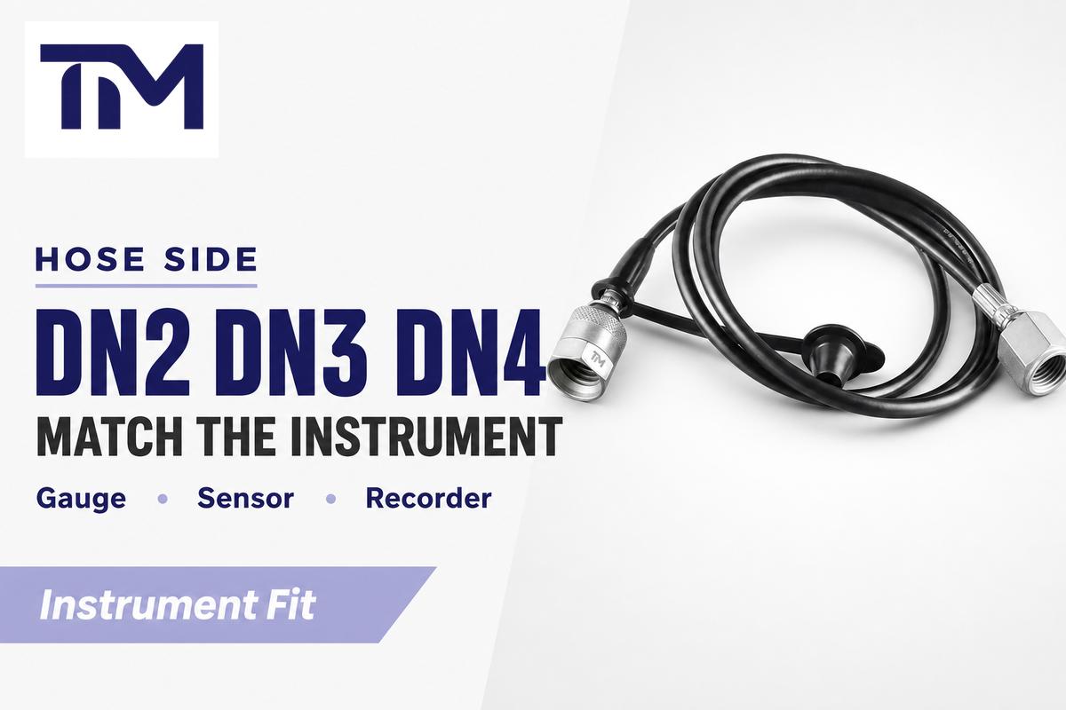
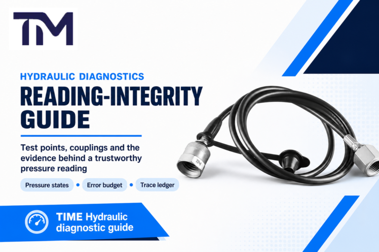
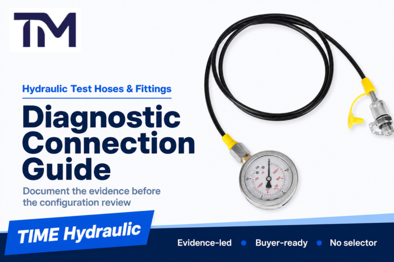
After the port side is known, check the hose side. A pressure gauge connector, sensor adapter, data recorder hose, or diagnostic kit may use a different end fitting than the machine port. Bore and length also affect handling, routing, fill volume, and response.
DN22 mm only when confirmed by drawing
DN44 mm only when confirmed by drawing
63 MPamaximum working pressure context stated by TIME
TIME also has product-family pages for DN2/DN3 microbore test hoses and DN4 hydraulic test hoses. Do not assign a DN3 millimeter value unless the exact drawing or supplier specification confirms it.
RFQ Thread Field Checklist
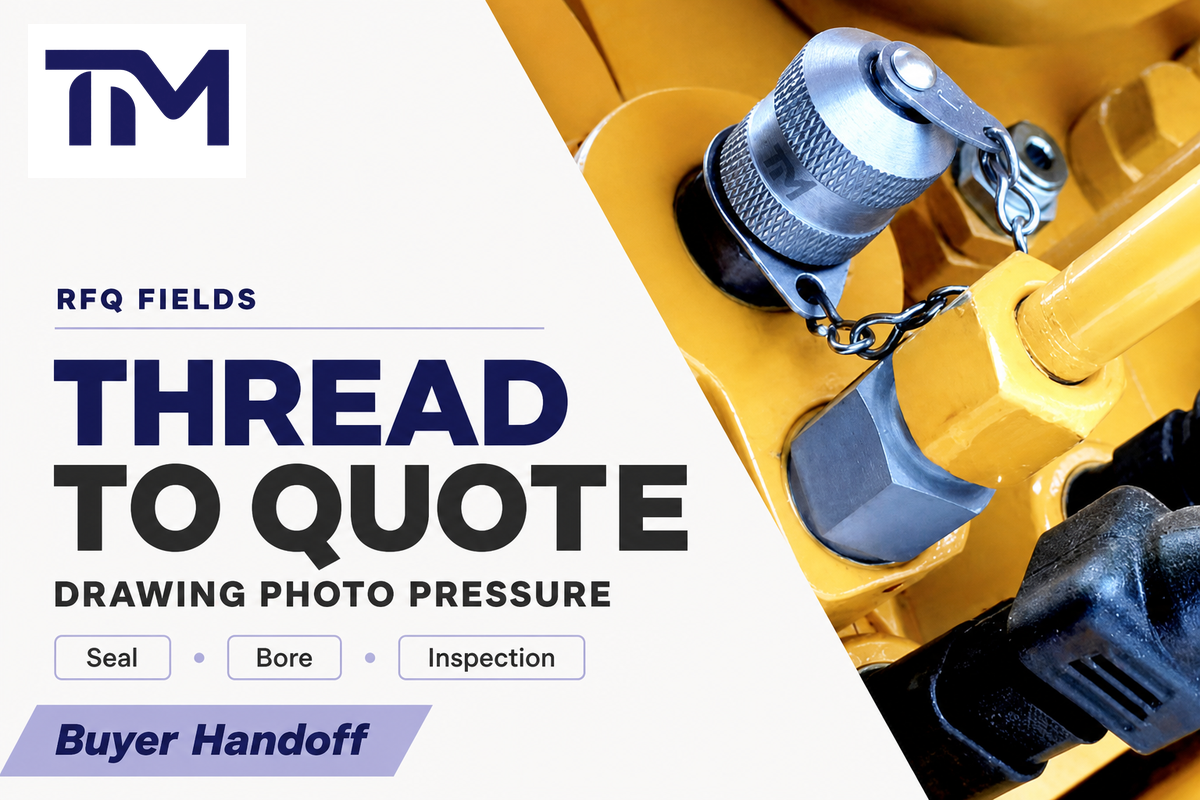
Beyond Thread Matching: Complete RFQ Requirements
Copy this RFQ Thread Field Checklist into the quote request when the maintenance team cannot provide a full drawing. It gives procurement a shared language for male and female sides, TIME, another supplier, or an internal engineering review. Matching is only the entry point; pressure class, bore size, hose length, fluid type, material, and inspection proof make the request safe enough to review.
RFQ Thread Field Checklist – copy these into your quote request:
| Category / type | Recommended entry | Why it matters | How to verify |
|---|---|---|---|
| Port standard | BSPP, BSPT, NPTF, metric, JIC, M16 x 2, or drawing code | Controls thread and seal family | Machine drawing or measured port |
| Side and size | Male or female, diameter, thread pitch or TPI | Prevents near-fit thread errors | Caliper plus pitch gauge |
| Seal style | Cone seat, O-ring, flare, face seal, washer, or tapered pipe | Thread fit does not prove sealing fit | Port photo, section drawing, or sample part |
| Pressure and use case | Working pressure, connection under pressure, gauge range | Keeps every part inside the pressure chain | Supplier datasheet and test requirement |
| Hose and instrument | DN2, DN3, DN4, hose length, gauge, sensor, data recorder, or kit | Connects the machine side to the measurement side | Instrument thread and hose routing check |
| Fluid and material | Mineral oil or exact fluid, seal material, stainless or plated steel | Protects compatibility and corrosion assumptions | Fluid data and supplier confirmation |
| Quality proof | Inspection report, material traceability, pressure test, warranty need | Makes quote comparison possible | Inspection record and certificate request |
| Commercial fields | Quantity, sample need, logo, packing, lead time | Keeps engineering and purchasing on one request | RFQ form or email checklist |
Need a connection check before ordering?
Send TIME the machine port photo, measurements, interface photo, pressure, hose bore, hose length, and instrument side. TIME’s team can review test hose end fittings and custom assemblies against the requested use case. Include any drawing code or standard marking so the review separates thread engagement from the sealing surface.
Common Mistakes That Cause Leaks, Wrong Readings, or Rework
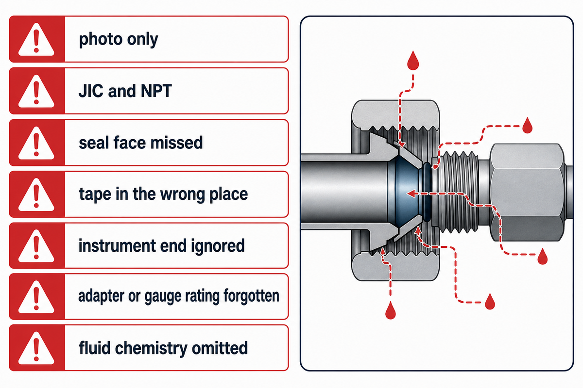
Most wrong orders come from reducing the connection to one clue. Avoid these errors when a machine is down and the team wants a fast replacement.
- Ordering by photo only, without diameter and pitch.
- Treating JIC and NPT as interchangeable because the nominal size looks close.
- Matching a thread but missing the O-ring, cone, flare, or washer interface.
- Using tape where the leak boundary is made somewhere else.
- Ignoring the gauge or sensor side on the instrument end.
- Using the hose pressure rating but forgetting the adapter or gauge rating.
- Leaving fluid chemistry and material out of the RFQ.
TIME Hydraulic Manufacturing Notes
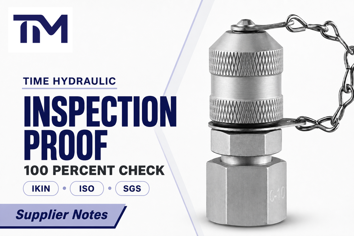
IKIN is the registered trademark, and TIME Hydraulic is the operating company. TIME specializes in test points and test hoses, with end fittings, custom test hose assemblies, and microbore hose families used for pressure measurement and diagnostic access.
TIME’s supplied brand information says TIME Hydraulic specializes exclusively in hydraulic test points and hoses, uses cone-seal and zero-leakage design practices, runs 100 percent inspection, keeps material traceability, holds ISO/SGS certification claims, operates a 5,000 square meter facility, has new workshops under development, and offers a 3-year quality warranty. Treat those items as supplier-approval fields: request current inspection records, certificate scope, issuing body, validity dates, and warranty terms before approving a production order. Public TIME first-party product references for test hose end fittings list BSP, NPT, metric, JIC, and M16 x 2 connection types, and buyer notes should keep ISO 15171-2, ISO 6149-2, ISO 9974-2, ISO 1179-2, and ISO 11926-2 in the same connection review context when those standards are mentioned.
For application-specific orders, review hydraulic test hose end fittings and custom test hose assemblies, then send the RFQ fields above for confirmation.
FAQ
What thread is used on hydraulic test connections?
There is no single universal thread. Test connections may use metric, BSPP, BSPT, NPTF, JIC, or M16 x 2 diagnostic families depending on the port, coupling, and interface design. Start with the installed port, not the spare hose in the tool box. Measure diameter and pitch, confirm straight or tapered form, identify the contact face, then verify pressure rating and instrument interface before ordering.
Are JIC and NPT threads the same on hydraulic fittings?
No. JIC uses a 37 degree flare sealing interface, while NPT and NPTF are tapered pipe-thread families. A close nominal size is not enough. Specify the family, size, side, sealing surface, pressure rating, mating part, final drawing, and pressure-chain check before purchase approval so procurement and maintenance approve the same connection.
How tight should a hydraulic test connection be?
Do not use a universal torque value. Tightness depends on family, interface design, material, size, lubrication, manufacturer instruction, and whether the seal is an O-ring, cone, flare, washer, or tapered thread. Over-tightening can damage threads, crush O-rings, or distort a cone seat; under-tightening can leak, loosen under vibration, or produce a false pressure reading. Verify the lowest-rated component with the adapter, gauge, and coupling when the test hose is installed on a live machine during maintenance, and recheck after installation.
Can I use thread tape on hydraulic test fittings?
Only when the specific tapered pipe-thread design and fluid service call for a compatible sealant. Avoid tape on O-ring, flare, cone-seat, and diagnostic coupler connections. If the drawing does not call for tape or paste, ask the supplier before assembly.
What should I send to TIME Hydraulic for a quote?
Send the port or thread standard, male or female side, diameter, pitch, straight or tapered form, seal style, pressure rating, hose bore, hose length, instrument interface, material, quantity, inspection needs, and drawing or photo. Add branding or packing needs if relevant.
Turn thread data into a quote-ready test hose specification
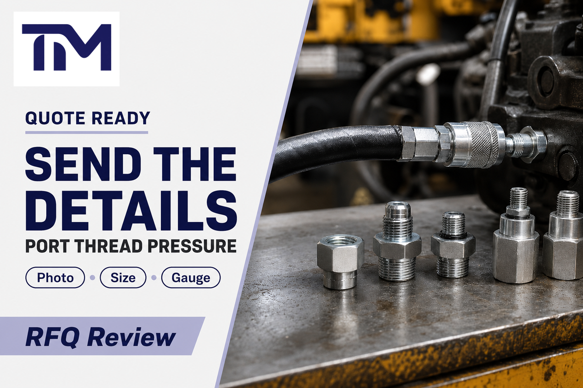
If you have a port photo, measured thread size, pressure requirement, and gauge or sensor connection, TIME can help match the test hose end fitting and custom assembly path.
References & Sources
- ISO 15171-2:2016 official page – diagnostic coupling scope, lifecycle status, pressure context, and fluid caveat.
- HSE Hydraulic injection injury safety alert – pressure, stored energy, compatible fittings, and medical-response context.
- ISO metric screw thread profile reference – diameter and pitch language for metric thread identification.
- ISO 6149-3 port stud-end reference – M14 x 1.5 stud-end context named in ISO diagnostic coupling material.
- TIME hydraulic test hose end fittings – connection types, seal styles, materials, inspection, warranty, and RFQ context.
- TIME custom test hose assemblies – DN2/DN4, pressure context, custom length, inspection, and warranty.
- Whyps thread identification background – measurement workflow and seal-family distinctions.
- NPT vs BSP thread background – NPT/BSP angle, form, sealing, and compatibility caution.