
Get in touch with TIME Company

DN2 & DN3 Microbore Test Hoses
- Engineer-reviewed quote within 96 hours
- Prototypes in 10-30 days after drawing approval
- ISO 2768-m general tolerances
- STEP or IGES models, DWG/DXF and dimensioned PDFs accepted
We build microbore hydraulic test hose assemblies in DN2 and DN3 sizes for pressure measurement at diagnostic test points. DN2 covers the tightest routing on mobile and industrial machines, while DN3 is a build-to-application bore for gauges that need to settle faster than a 2 mm line allows. Send the port thread, the length and the pressure you measure at.
Your drawings are handled as confidential. We sign a mutual NDA on request before you send anything.
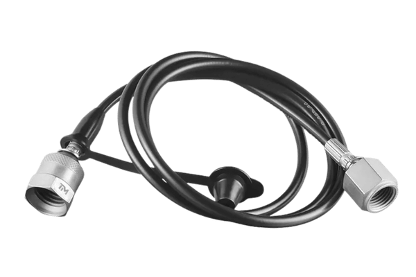
Microbore Hose Bore Sizes: DN2, DN3 and DN4 Compared
Bore size settles three questions at once: how much pressure the line holds, whether it bends into the space you have, and how long the gauge takes to settle. Whichever of the three runs out first sets the bore step you need; we call that sequence the Bore Step Method.
CLICK TO PIN VIEW
The Rating Belongs to the Assembly, Not to the Hose
A pressure figure printed on a hose is not the rating of the finished assembly. Hydrotechnik states the rule plainly: the lowest pressure of hose or fitting determines the maximum operating pressure of the complete assembly. This is where buyers get caught out — New-Line marks its micro hose crimp couplings for installation by a factory certified assembler only.
Dash Numbers Do Not Carry a DN Value
Dash numbers count sixteenths of an inch of nominal bore and belong to a different naming system from DN, so a dash figure tells you nothing reliable about which DN bore it mates with. That is where many mis-orders start.
- Give the bore in millimetres and the thread by its designation — the marking and the bore are independent.
- When replacing an assembly, measure the hose bore rather than reading the fitting code.
Where the DN3 Bore Fits
DN3 is not a catalogue size: the manufacturers who set the pattern publish DN2 and DN4 and step over the middle, which is why a search for DN3 pressure data comes back empty.
ISO 1307:2006, the standard that sets inside-diameter ranges for rubber and plastics hoses, states that it is intended to be used with the relevant hose product standard unless there is justification for using a different hose size, or unless a hose size needs a different inside-diameter range for a particular application. That clause sets no test for what counts as justification and endorses no particular size, so read it as the standard acknowledging that non-listed bores exist rather than as approval of DN3.
Request the DN3 data sheet for your pressure and routing →Flow Area and Fill Volume Across DN2, DN3 and DN4
| Bore Step Table | DN2 | DN3 | DN4 | Basis |
|---|---|---|---|---|
| Nominal inside diameter | 2 mm (0.079 in) | 3 mm (0.118 in) | 4 mm (0.157 in) | DN naming convention |
| Flow area | 3.14 mm² | 7.07 mm² | 12.57 mm² | Geometry |
| Flow area against DN2 | 1.00× | 2.25× | 4.00× | Geometry |
| Fill volume per metre of hose | 3.14 mL | 7.07 mL | 12.57 mL | Geometry |
| Fill volume of a 2,000 mm assembly | 6.3 mL | 14.1 mL | 25.1 mL | Geometry |
| Relative pressure drop at the same flow rate | 1.00× | 0.20× | 0.06× | Fourth-power relation, laminar |
| Relative flow at the same pressure drop | 1.00× | 5.06× | 16.0× | Fourth-power relation, laminar |
| Minimum bend radius published for the bore | 20 mm, 30 mm below −20 °C | To drawing | 40 mm | MINIMESS DN2/DN4 data sheet |
| Working and burst pressure | See the ratings table below | To drawing | See the ratings table below | Manufacturer data sheets |
The fourth-power rows hold under stated conditions: laminar flow of an incompressible fluid with length, viscosity and pressure difference otherwise unchanged, as Harvard’s lecture demonstration on Poiseuille’s law puts it. Read them as a comparison of resistance between bores, not a description of a hose in service: a diagnostic line is dead-ended, so resistance follows the fourth power while the volume it must fill follows the square of the bore.
Every row above is worked live in the Bore Step Calculator: enter a bore and an assembly length for flow area, fill volume and the resistance comparison against DN2.
Test Hose Construction and Reinforcement Materials
Three suppliers describe microbore test hose three different ways — reinforced rubber, synthetic fibre braid, aramid braid — and buyers reasonably conclude that someone is wrong. Nobody is: those are pressure classes of one product family, separated by the reinforcement.
Thermoplastic Liner
- Common systems
- Polyamide (nylon), polyurethane, PTFE and rubber liners are all used in this product family
- Why engineers pick it
- A thermoplastic liner holds a 2-3 mm bore round under pressure and keeps the wall thin enough to stay flexible in a tight radius, which is where a microbore assembly’s routing flexibility comes from
Braid Reinforcement
- Common systems
- Synthetic textile braid and aramid braid
- Why engineers pick it
- Sarum Hydraulics puts textile braid at around 407 bar and identifies aramid as the reinforcement that carries a 630 bar rating — the single biggest step in what a microbore hose can hold
Fitting Steel and Plating
- Common systems
- Zinc-plated and nickel-plated steel
- Why engineers pick it
- Plated steel carries the crimp load at the lowest cost per assembly and suits enclosed installations
Stainless Steel
- Grades
- 304, 316 and 316L, plus the V2A and V4A designations used in European catalogues
- Why engineers pick it
- Grade matters more than the word stainless: 316 is the marine-duty choice, while 303 and 304 are the general-purpose grades. Sarum makes the point that the grade has to be specified, not assumed
Seals, and Confirming the Construction in Writing
Seal material is called out on the drawing rather than assumed. ISO 15171-2:2016 scopes this coupling family to hydraulic systems using mineral oil, which is why NBR (Buna-N) is the default seal and why another fluid calls for a written agreement between supplier and purchaser — FKM is the usual alternative where the port runs hotter. We confirm the liner, reinforcement, seal and fitting material in writing with the quotation before anything is cut.
Test Point Connections, Gauge Threads and Compatible Adapters
Settle the thread first, not the pressure. Buyers working across machines from several builders hit thread mismatch long before a pressure limit, and a hose that cannot land on the port is worth nothing whatever it is rated at. Each connector below is listed by its thread designation first.
Why M16×2 Dominates the Test Point
- ISO 15171-1 covers push-pull diagnostic couplings, the ones you press on.
- ISO 15171-2 covers the screw-to-connect coupling with the M16×2 end, the thread most machine builders standardised on.
- The same M16×2 test point is sold as Minimess® in one country and as Test 20 in another.
- Connecting a gauge through a direct adaptor rather than a hose still needs a hose union between the two, a detail HydraCheck flags on its own product pages.
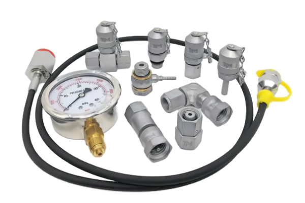
Stud Ends the M16×2 Coupling Is Built to Meet
ISO 15171-2:2016 lists the port stud ends this coupling family is dimensioned against. If your port is one of these four, the question is answered.
| Stud end standard | Thread | Where you meet it |
|---|---|---|
| ISO 6149-2 | M14×1.5 | Metric ports with an O-ring seal, common on newer machine builds |
| ISO 9974-2 | M14×1.5 | Metric ports on general hydraulic equipment |
| ISO 1179-2 | G 1/4 | BSPP ports across European equipment |
| ISO 11926-2 | 7/16-20 UNF | UN/UNF ports across North American equipment |
The Marking-to-Thread Decoder turns a stamped marking into the thread it actually is and matches the stud ends above to it, including the markings in this series that are a different thread.
Connection Types We Terminate
| Connection | Thread or form | Where it is used |
|---|---|---|
| Test point with stud connection | M16×2 test coupling body | Permanent tapping point in the machine |
| Stainless steel test point | 304 and 316L bodies | Washdown, marine and outdoor |
| Test coupling with JIC 37° connection | SAE J514 flare | North American hose and tube |
| Test point with DKO 24° male cone | Metric internal cone | European tube systems |
| Test coupling with cutting ring | Metric compression | Rigid tube without re-flaring |
| Fittings with O-ring or flat seal | Soft-seal face | Repeated disconnection at gauges |
| Banjo connection fittings | Bolt-through eye | No room for a straight take-off |
| Tee and tube connections | Metric and BSPP bodies | Reading a live circuit without breaking it |
| Male thread fittings with stud connection | BSPP, metric and NPT | Adapting to an existing gauge thread |
New-Line splits its diagnostic range into NPT and ORB kits for North America and BSP and metric kits for Europe, the same split we quote against. Where both meet on one machine, adapt rather than improvise — a tapered pipe thread will damage the port it is forced into long before the hose gives up. Send the port designation and the adaptor question is closed in the quotation.
Standard Assembly Lengths and What Each One Is For
| Length | Where it fits |
|---|---|
| 200 mm | Gauge mounted straight at the test point |
| 400 mm | Two adjacent ports on one valve block |
| 630 mm | Pump or valve block to a hand-held gauge |
| 800 mm | Out of a crowded valve bank to a readable position |
| 1,000 mm | Bench and workshop test rigs |
| 1,500 mm | Cab-side reading on mobile equipment |
| 2,000 mm | Operator at the controls, sensing point on the machine |
| 2,500 mm | Engine bay to service hatch on larger machines |
| 3,200 mm | Wheeled test cart standing clear of the machine |
| 4,000 mm | Panel gauges reading a remote sensing point |
These ten bands are published in the STAUFF Anglia test hose catalogue and are the lengths that quote and ship fastest. Lengths between them are a drawing item.
Working Pressure, Flow Capacity and Temperature Limits
Two pressure numbers govern a diagnostic line: how much pressure the coupling will connect against with no tools, and how much the connected assembly holds in service. Reading them as one figure is the most common pressure mistake on a test point.
Working Pressure and Connection-Under-Pressure Limits
| Limit | Value | What it governs |
|---|---|---|
| Connection under pressure, without tools | 40 MPa (400 bar) | The pressure you are allowed to connect against while the circuit is live |
| Maximum working pressure of the coupling | 63 MPa (630 bar) | The pressure the connected assembly holds in service |
Both figures are stated in ISO 15171-2:2016 for the M16×2 diagnostic coupling, and the standard qualifies the working pressure itself: it depends on the materials, design, working conditions and application. That is why the assembly rating, not the hose print, is the number to design to.
Published Ratings for the DN2 Bore
| Source | Working pressure | Minimum burst | Bore × outside diameter | Minimum bend radius |
|---|---|---|---|---|
| MINIMESS DN2 data sheet (Hydrotechnik) | 400 bar standard, 630 bar high-pressure | 1,040 bar and 1,950 bar respectively | 2 mm × 5 mm | 20 mm, 30 mm below −20 °C |
| STAUFF Anglia test hose catalogue | 400 bar standard, 630 bar high-pressure (9,135 psi) | 1,100 bar and 1,900 bar respectively | 2 mm bore, cover diameter by hose type | Per catalogue entry |
Read those rows across rather than down: each burst minimum belongs to the working pressure printed beside it, and the two vendors disagree because these are two manufacturers’ products, not one category constant. ISO 7751:2016 sets minimum ratios of proof and burst pressure to maximum working pressure by hose service category, which is why the honest answer to the safety-factor question is construction-specific rather than a slogan; STAUFF accordingly prints a test pressure against each type, 600 bar for the 400 bar hose and 950 bar for the 630 bar one.
Temperature Derating and Media Limits
A pressure rating printed on a test hose is a rating at 50 °C, and the MINIMESS data sheet puts the hose’s service range at −20 °C to +100 °C with short-time excursions to +120 °C. Both catalogues publish the same utilisation factors across the range they share — the convention this family is quoted on, though two catalogues agreeing is not a standard requiring it. Confirm the figures against the data sheet for the construction you are buying.
| Fluid temperature | Pressure utilisation factor | 400 bar type, as printed | 630 bar type, same factors applied |
|---|---|---|---|
| 0 °C | 122% | 488 bar | 769 bar |
| 30 °C | 110% | 440 bar | 693 bar |
| 50 °C | 100% | 400 bar | 630 bar |
| 80 °C | 86% | 344 bar | 542 bar |
| 100 °C | 77% | 308 bar | 485 bar |
| 120 °C (short time only) | 68% | Not published | 428 bar |
The percentage series and the 120 °C row are published by Hydrotechnik, whose data sheet prints 693 bar at 30 °C for the high-pressure hose; the STAUFF Anglia catalogue prints the same factors as absolute values against its 400 bar type and stops at 100 °C. Tell us the fluid at enquiry, and the mineral-oil agreement required by ISO 15171-2:2016 becomes part of the quotation.
The Temperature Derating Calculator applies this series to either printed type at the fluid temperature you measure, interpolating between the published rows.
Hydraulic Hose Assembly Quotation, MOQ, Samples and Lead Times
We do not publish a unit price for built-to-drawing assemblies: a single figure would be wrong for most enquiries the moment it is printed. What we can publish is the structure behind it.
What Moves Your Price
| Driver | Effect on cost | How to reduce it |
|---|---|---|
| End fitting configuration | Two different ends cost more than two identical ends, in parts and setup | Use the same test point thread at both ends where the routing allows |
| Reinforcement class | Aramid for a 630 bar rating sits above textile braid for a 400 bar rating | Rate the line to the circuit you measure, not to the highest number on the machine |
| Fitting material | Stainless steel bodies cost more than plated steel | Reserve stainless for the connections that actually see washdown or salt |
| Length and quantity | Non-standard lengths add setup; small runs carry it across fewer pieces | Work from the standard bands and consolidate variants into one order |
How Your Quotation Is Produced
Quotes are reviewed by an engineer and returned within 96 hours on business days. We work from STEP or IGES 3D models, DWG/DXF 2D drawings and dimensioned PDFs — or a physical sample when no CAD exists.
Lead Times by Order Stage
| Order stage | Lead time | What it covers |
|---|---|---|
| Prototype | 10-30 days after drawing approval | First articles for fit and pressure verification |
| Small batch | 30-60 days after drawing approval | Pilot quantities against the approved first article |
| Production | 30-60 days, confirmed with your quotation | Repeat runs scheduled against your release |
Order Terms
| Term | What we commit to |
|---|---|
| Minimum order | There is no fixed minimum order for stocked items, and single pieces are accepted for trial fitting. Re-produced and custom items run in batches of 300-500 pcs |
| Samples | Samples are built from your drawing. Sample quantities under 5 pcs are free for quality verification, and samples against a custom drawing are quoted |
| Expediting | Rush orders are accepted case by case; expect the schedule to tighten by a few days rather than halve, and air freight is available when the date is critical |
| Payment | 30% T/T deposit, 70% T/T balance before shipment, by wire transfer |
| Incoterms | We ship FOB and EXW as standard, with CIF and CFR available on request |
Inspection, Certification and Warranty for Every Hose Unit
Every assembly is 100% inspected before it ships, under a three-year warranty. A packing list, a material certificate and a pressure test report ship with your order, with a certificate of conformity and a full dimensional inspection report on request.
If an Assembly Does Not Meet the Drawing
Most warranty arguments start the same way: an assembly failed in service and nobody can say which step let it through. That is a records problem before it is a parts problem, so the route below is written to come out of the batch record.
- 01 Send the assembly identification and the fault, with the pressure and port it was fitted to.
- 02 We check it against the drawing and the pressure test record for that batch.
- 03 Outside the drawing, we rework or remake it against the same written acceptance criteria used at first inspection.
- 04 Where the drawing no longer matches the machine, we requote the corrected build rather than shipping the same part twice.
What to Ask Any Test Hose Supplier
These are the questions that separate a supplier with a real process from one with a badge. Use them on us as readily as on anyone else.
| Ask this | Why it separates suppliers |
|---|---|
| Which method does your pressure test report follow? | ISO 1402:2021, the current fifth edition, specifies methods for the hydrostatic testing of rubber and plastics hoses and hose assemblies, including determination of dimensional stability |
| What is sampled and what is checked on every piece? | STAUFF publishes its own frequencies for DN2 and DN4 test hose: length on the first piece and every 25th, crimp diameter on the first and last piece, flow-through on the first piece and every 10th with 100% on elbow fittings, and pressure testing on the same basis |
| How is an over-crimped assembly caught? | STAUFF supplies go/no-go gauges for DN2 and DN4 and scraps the assembly when the no-go end enters — a discard rule already decided, not one taken under delivery pressure |
| Who is audited, and against what scheme? | The BFPA Approved Hose Assemblies Scheme, running since 1995, audits assembly and manufacture, storage and supply, workshop facilities, mobile service operations and staff competence, with independent audits about every two years |
| Who issued the certificate and how do I verify it? | ISO states that it does not perform certification or issue certificates and that a company cannot be certified by ISO — certification is carried out by external bodies. Verify a certificate with the certification body, the accreditation body, or the database now run by Global Accreditation Cooperation Incorporated, which took over the former IAF and ILAC roles |
We would rather lose a quote than print a figure we cannot trace back to a drawing and a test record. Put those five questions to us as hard as you put them to anyone else.
From Enquiry to Delivered Hose Assemblies
1.Send the requirement
port thread, bore, length and the pressure you measure at, with a drawing, a 3D model or a physical part.
Engineering review
we check thread and stud end against your port, flag anything that will not seal, and return the quotation.
Drawing approval
the build drawing is confirmed in writing, and that approval starts the clock.
Prototype build
first articles for fit and pressure verification before quantity is committed.
Batch production and inspection
assemblies are crimped, gauged and pressure tested, and we carry the result rather than passing it on.
6.Packing and shipment
the documents above travel with the batch, on the Incoterms agreed in the quotation.
Machining and assembly stay in-house. Where a specialised step runs outside — heat treatment or plating — it goes only to an approved shop working to the same inspection standard and bound by the same confidentiality terms, and a routing document follows the batch through every operation so an outsourced lot stays traceable.
Manufacturing Base and Hydraulic Systems Supply Record
TIME Hydraulic manufactures under the IKIN registered trademark from a 5,000 m² plant, with a further workshop under construction. Cone-seal geometry designed for zero leakage is the basis of the test point range, and every assembly leaves under the inspection and warranty terms set out above.
Mobile equipment — excavators, loaders and cranes.
Industrial hydraulics — presses, injection moulding and steel plant.
Test and service workshops — bench rigs and wheeled test carts.
OEM and distribution programmes supplied against a release schedule.
Hydraulic systems and component manufacturers we supply include SANY, XCMG, Parker, HAWE, GE, Rexroth and Caterpillar.

Cases Where a Larger Hydraulic Hose Bore Is the Better Choice
A microbore line is a sensing line. Asked to do something else, the honest answer is a different product rather than a bigger promise. The trade-off is physics: every millimetre of bore you give up buys tighter routing and costs response time, and there is a point where that stops being worth paying for.
| Situation | Why it works against you | What to do instead |
|---|---|---|
| The line has to carry working flow, not sense pressure | At a 2-3 mm bore the pressure drop dominates and the reading stops representing the circuit | Move to DN4 or a full-bore line sized for the flow |
| There is room for a 40 mm bend radius over a long run | The smaller bore buys you nothing and costs you response time | Specify DN4 and keep microbore for the tight sections |
| Continuous duty on a power circuit rather than intermittent diagnostic access | A diagnostic assembly is built for connection and disconnection, not for permanent load cycling | Use a power hose rated for continuous duty and leave the test point for measurement |
| An existing assembly has failed and the plan is to re-end it | Re-ending — cutting off a failed end and crimping a new one onto used hose — is named by the BFPA hose scheme as an unsafe practice its approval scheme exists to eliminate | Replace the assembly and keep the failed one for diagnosis |
Engineering Tools for DN2 & DN3 Assemblies
Bore Step Calculator
Compare flow area, fill volume, and resistance across DN2, DN3, and DN4 bores for diagnostic routing.
Launch Tool
→
Temperature Derating Calculator
Apply pressure utilisation factors to verify assembly holding capacity at your measured fluid temperature.
Launch Tool
→
Marking-to-Thread Decoder
Turn stamped coupling markings into true thread standards to identify the correct port stud ends.
Launch Tool
→
Request Drawings, Samples or a DN3 Quotation
Two routes in: standard DN2 configurations quote from the port thread and length; DN3 and non-standard builds start from a drawing review.
Request the DN2 and DN3 data sheet — no phone number required.
Free samples up to 5 pcs for quality verification before you commit to a batch.
A formal quotation reviewed by an engineer, returned within 96 hours.
— KNOWLEDGE BASE
Frequently Asked Questions
It is a small-bore hydraulic hose assembly, usually 2 mm to 4 mm inside diameter, built to connect a pressure gauge or transducer to a diagnostic test point. It senses pressure rather than delivering flow.
Test 20 is the M16×2 thread in the STAUFF marking system, so an M16×2 coupling lands on a Test 20 port. Neighbouring markings are different threads: Test 15 is M16×1.5, Test 12 is S12.65×1.5, and Test 10 has no thread.
The MINIMESS DN2 data sheet gives 20 mm, rising to 30 mm below −20 °C, and a stainless-braided PTFE variant at 13 mm. Bend radius is a property of the construction rather than of the bore, so confirm it against the exact hose type being quoted. Send the tightest corner on the intended route with the enquiry.
Because no manufacturer publishes one. DN3 is a build-to-application bore rather than a catalogue size, so working pressure, burst pressure and bend radius come back with your drawing. Printing a figure here would mean interpolating between two published DN2 constructions that already disagree across a 1,040 to 1,950 bar span on minimum burst, and an interpolated number is worse than none when a safety case rests on it.
That combination needs an adaptor rather than a matched pair. A 14 DIN L male stud is a light-series metric tube end on a 14 mm outside diameter while a 1/4 inch NPT female port is a tapered American pipe thread; they are not interchangeable, and will appear to start together for a turn before they bind. Send both port designations with the enquiry and the adaptor is specified in the quotation.
