Get in touch with TIME Company


Updated August 2026 · Maintenance, reliability and technical procurement guide
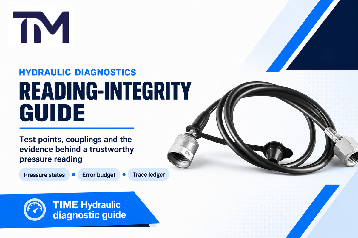
Hydraulic Test Points & Couplings are diagnostic access components that create a temporary route between a pressurized system and test equipment, but a connection that physically fits does not automatically make the work permitted or the reading trustworthy. A defensible result depends on the installed port, test point, mating coupling, hose or adapter, instrument, operating state, and the procedure that joins them.
This guide addresses three questions that product catalogues often leave separate: may the connection be made in the present pressure state, can the resulting measurement answer the fault question, and is the record complete enough for another person to review? It does not duplicate model families, general test-point selection, thread identification, quotation, or supplier capability. Those remain with the site’s commercial and specialist pages.
The short answer
A hydraulic test point is the installed access interface; the coupling is the mating connection used to attach a hose, adapter, pressure gauge, sensor, or meter. The same evidence chain applies to diagnostic couplings, test point fittings, a pressure tester, and other measuring and display devices. Treat the complete temporary measurement route as one documented chain, while checking pressure-state permission and measurement validity as separate decisions.
What a Hydraulic Diagnostic Connection Must Prove
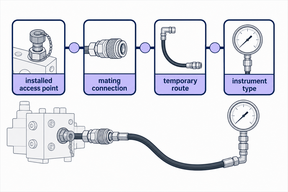
A valid diagnostic connection must prove the identity and condition of every interface from the machine port to the instrument. One diagnostic route may place an installed test-point nipple on one side and a mating diagnostic coupler plus gauge or diagnostic equipment on the other. Record port connections and adapters as distinct interfaces. That topology describes the route; it does not approve an unnamed mixed-brand assembly.
Map Sources of Reading Error Before Testing
Trace the route by the evidence each position can add to, or remove from, the measurement:
- Locate the measurement — record the circuit function, machine state, medium, temperature, and exact port drawing.
- Identify the installed access point — record the test-point family, stud end, seal, material, condition, and documented limits.
- Verify the mating connection — check the test connector or coupling family and maker-documented mating relationship, not just the visible thread.
- Trace the temporary route — include every test hose, adapter (including any gauge adapter), reducer, restraint, and connection exposed during the test; use the diagnostic connection evidence guide for assembly-level checks.
- Define the instrument — record the instrument type, including the pressure monitoring instrument type where applicable, range, overpressure limit, accuracy basis, calibration evidence, units, and logging configuration.
Before mating the route, inspect and protect the cleaned ends to prevent contamination. Record any contamination, damaged cap, leakage, or disturbed sealing face as a condition that can affect the system or the test evidence.
Record whether the test location sits before or after a flow control, check valve, or ball valve because component state changes what the reading represents. A protective metal cap, corrosion, or damage at the access point belongs in the condition record; resistance to corrosion cannot be inferred from appearance alone.
A bulkhead location, swivel, or direct gauge adaptor can change support and routing. Record each item as part of the configured route without assuming a better or worse rating.
Use the lowest documented pressure capability as an arithmetic boundary across the complete chain but don’t mistake that number for a permission decision. Positive margin can’t prove fluid compatibility, seal geometry, mechanical retention, routing, calibration, dynamic response, or permission to connect under pressure. Damaged hoses, unsupported adapters, sharp bends, abrasion, or a poorly secured instrument can also create separation and fluid-release hazards that the test-point rating alone can’t control.
If any required drawing, rating, fluid statement or instruction is missing mark it unknown. An unknown field isn’t zero risk and isn’t a reason to borrow a value from a similar-looking product.
Separate Three Pressure States Before You Trust a Reading
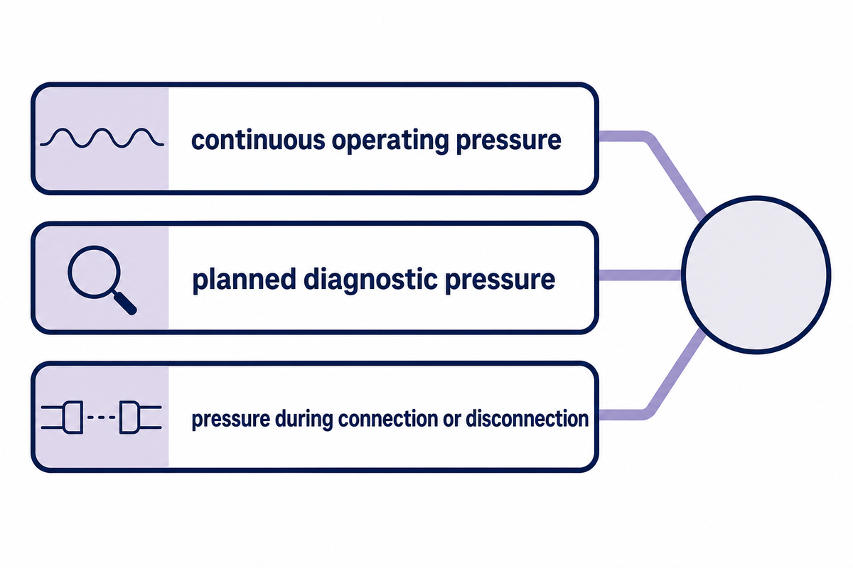
Connection permission depends on three distinct pressure states: continuous operating pressure or working pressure, planned diagnostic pressure, and hydraulic system pressure during connection or disconnection. The overlap must also include interface evidence, fluid and temperature compatibility, exact product instructions, and the controlling work procedure.
Physical fit and one attractive rating are only fragments of that decision. A working-pressure value does not automatically permit mating at that pressure, while an allowed connection state does not prove that the complete temporary route can withstand the planned steady and transient test conditions.
Three-state rule: document each pressure state separately and mark an unavailable value as unknown. Do not copy a limit from a similar-looking interface or use one state as a substitute for another.
Stored Energy and Fluid-Injection Stop Conditions
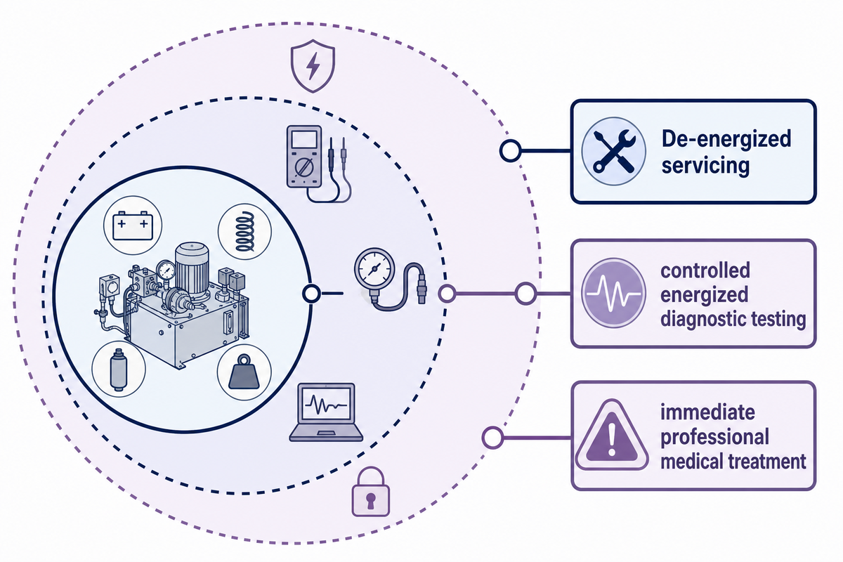
De-energized servicing and controlled energized diagnostic testing are different task states and need different controls. “Switch the machine off” isn’t evidence that hydraulic accumulators, suspended loads, trapped volumes, or pressure between valves have been rendered safe. But “always remove all pressure before any test” is also too broad: some fault reproduction requires an energized operating state.
For US servicing and maintenance, OSHA 1910.147(f)(1) distinguishes temporary energization for testing or positioning. Its sequence requires clearing tools and materials, removing employees from the area, removing the energy-control devices as specified, energizing for the test, and then de-energizing and reapplying energy controls before servicing continues. Machine operators and maintenance personnel still follow the authorized site procedure. This is a regulatory boundary, not a substitute for the machine-specific procedure or qualified site supervision.
Do
- Classify the task as servicing, inspection, or controlled energized testing.
- Identify every hazardous energy source and possible reaccumulation path.
- Use the approved sequence for isolation, verification, test, and restoration.
- Inspect the complete temporary measurement assembly before use.
Don’t
- Treat shutdown, a zero display, or one open valve as complete verification.
- Search for leaks with hands or expose skin to a suspected jet.
- Use a generic pressure number as an injection-safety threshold.
- Connect or disconnect because the interface merely appears compatible.
The UK Health and Safety Executive documents a fatal incident caused by significant stored energy. It notes serious reported injection injuries above 100 bar (1,450 psi) and describes 7 bar (101.5 psi) only as anecdotal evidence. That lower figure isn’t a safe threshold: injury severity also varies with proximity and jet size, while the fluid itself can add toxic harm. Suspected injection requires immediate professional medical treatment even when the skin wound looks small.
The Port-to-Reading Error Budget
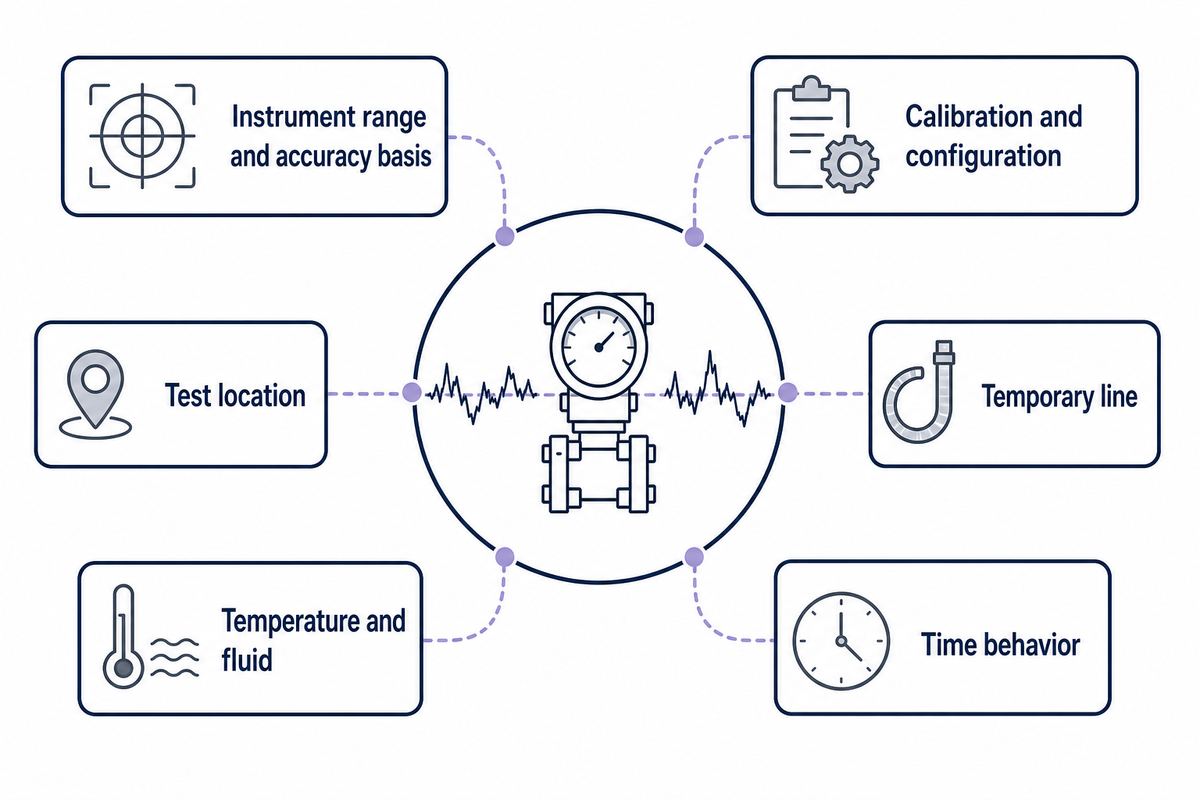
A permitted connection can still produce a misleading result because the instrument reads the behavior of the entire configured route, not an abstract pressure value at the port. Once the procedure controls stored-energy and fluid-injection risks, build an error budget as an evidence worksheet: list each influence, its documentation, the expected measurement effect, and whether it’s known, bounded, or unresolved.
| Influence | Evidence to record | Diagnostic consequence |
|---|---|---|
| Instrument range and accuracy basis | Range, resolution, percent-of-reading or percent-of-full-scale specification. | An oversized full-scale range can make a small absolute change hard to interpret. |
| Calibration and configuration | Instrument ID, certificate/status, units, zeroing, sample rate, filters, and channels. | Current calibration does not prove the selected setup or range suits the test. |
| Test location | Circuit point, valve state, load, pump state, and nearby restrictions. | Pressure at one point may not answer what happens at another component. |
| Temporary line | Length, bore, route, adapters, fill state, trapped gas check, and damage inspection. | Dynamic response may change; do not invent a universal correction. |
| Temperature and fluid | Fluid identity, temperature, warm-up state, viscosity-sensitive conditions. | Instrument, hose, seals, and system behavior can change with conditions. |
| Time behavior | Start time, stabilization observation, peaks, oscillation, logging duration, and repeat. | One screenshot can conceal transients or an unsettled reading. |
NIST Technical Note 1994 demonstrates that tubing can create frequency-dependent amplitude change and phase shift in a dynamic pressure system. Its application is aerodynamic, so its equations aren’t transferred to field hydraulics. The useful lesson is narrower: dynamic line effects are configuration-specific. They don’t prove that every hose creates a material steady-state offset, and they can’t be repaired with one generic factor.
Instrument notation also needs translation into the result. As a specification example, a 100 psi gauge rated at 0.1% of full scale has a stated absolute band of ±0.1 psi across that range. The arithmetic illustrates why range matters; it isn’t a selection rule or an uncertainty budget for the complete hydraulic setup.
Worked example: translate a full-scale rating into the displayed result
For an illustrative 250 bar full-scale instrument rated at 1.0% of full scale, the arithmetic band is ±2.5 bar. At a displayed 25 bar, that band equals ±10% of the reading; at 200 bar, it equals ±1.25%. If the same example logs at 100 Hz for 10 s, the file contains 1,000 samples before any filtering or rejected data are considered. At 50 Hz for the same 10 s, it records 500 samples; at 75 Hz, 750 samples. These values demonstrate the calculation only; they do not describe an IKIN product or replace product-specific accuracy, calibration, and dynamic-response evidence.
What makes a hydraulic pressure reading trustworthy?
A trustworthy reading has a known connection chain, a suitable instrument range, current calibration evidence, controlled operating conditions, observed time behavior, and a record of uncertainty and unknowns. Repeat the measurement under the same defined state when repeatability matters. If the reading changes after the hose is attached, investigate configuration, trapped gas, leakage, restriction, location, and stabilization instead of immediately applying a correction.
When Pressure Alone Is Not Enough
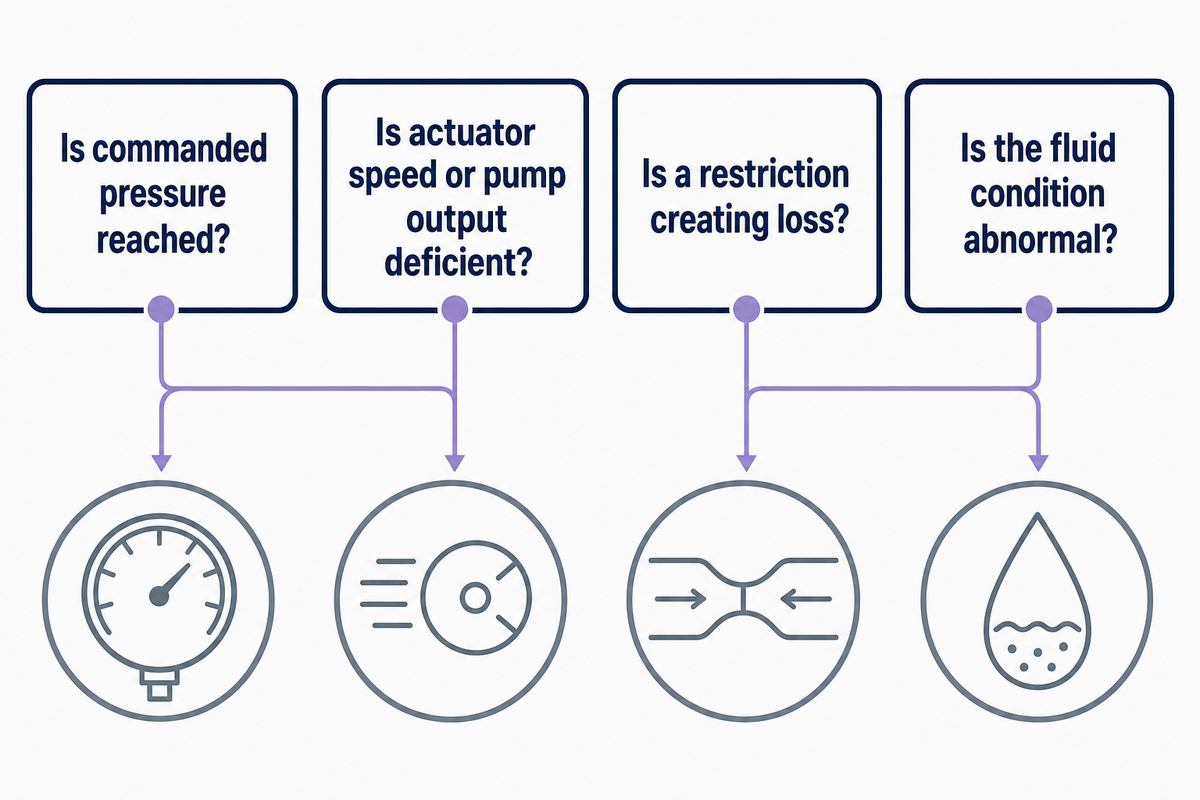
Choose measurements from the fault question rather than from the access hardware already available. Pressure can confirm that a condition exists at a location and time. It may not show whether the pump supplies the required flow, whether a restriction is producing excessive heat, or whether fluid condition is contributing to wear.
| Fault question | Useful observations | Boundary |
|---|---|---|
| Is commanded pressure reached? | Pressure, load state, command, time trace. | Peak pressure may not prove sustained performance. |
| Is actuator speed or pump output deficient? | Flow with pressure, temperature, command, and speed/load context. | Normal pressure can coexist with insufficient flow. |
| Is a restriction creating loss? | Pressure at defined upstream/downstream points, flow, and temperature. | Non-simultaneous readings may miss a changing state. |
| Is the fluid condition abnormal? | Representative sample under a documented sampling method. | Pressure access alone does not prove sample quality. |
A Fluid Power Journal case illustrates this conditional logic: engineers concluded that pressure alone was insufficient and measured flows, pressures, and temperatures together. It’s an attributed case, not a requirement that every diagnostic job use all three variables.
A mechanically usable pressure port can still be a poor oil-sampling location. Keep that distinction brief here; use the fluid sampling and diagnostic test points application guide for sampling location, cleanliness, operating-state, and collection-method decisions.
Standards Define a Boundary, Not a Mating Approval
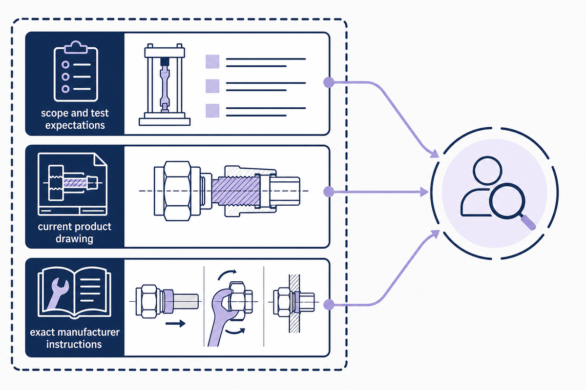
A standards reference defines scope and test expectations; it does not automatically approve two brands as a mating pair. Use the edition, part, interface dimensions, current product drawing, fluid scope, pressure state, and exact manufacturer instructions together. Dimensional familiarity is evidence to continue checking, not a completed compatibility decision.
The public records illustrate why those labels stay separate: ISO 15171-2 lists a maximum connection-under-pressure value of 40 MPa (400 bar) within its specified M16 × 2 scope and a conditional 63 MPa (630 bar) working figure, while SAE J1502 lists a conditional 42 MPa (420 bar) working figure. Whether a pressure test coupling may be connected under pressure remains product- and state-specific.
Route thread identification to the hydraulic test thread guide and ISO Part 2 interpretation to the ISO 15171-2 compatibility guide. Those specialist pages own the detailed interface and standard questions; this guide uses only the measurement boundary.
Build a Test-State Measurement Trace Ledger
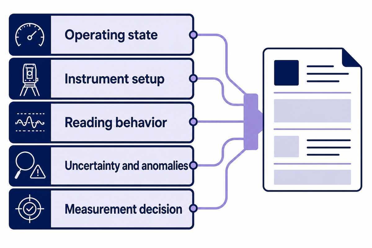
A diagnostic result is reviewable only when another person can identify what was measured, in which operating state, with which instrument setup, and over what time behavior. That standards boundary must remain visible in the measurement record. A single pressure value or dashboard screenshot cannot show those conditions or the uncertainty that remains.
Use this Test-State Measurement Trace Ledger as an editorial worksheet, not as an industry standard or substitute for an authorized procedure:
| Record category | Required fields | Why the reviewer needs it |
|---|---|---|
| Location and question | Asset ID, exact circuit point, component function, fault question. | Defines what the observation can answer. |
| Operating state | Mode, load, command, speed, temperature, controls, test start time. | Separates results taken under different conditions. |
| Instrument setup | Instrument ID, range, accuracy basis, calibration status, units, sample rate, filters. | Makes the displayed value and configuration reviewable. |
| Pressure-state record | Continuous working, planned diagnostic, and connection or disconnection pressure. | Prevents one pressure state from standing in for another. |
| Reading behavior | Steady value, peaks, oscillation, stabilization time, logging duration. | Prevents one screenshot from hiding transient behavior. |
| Repeatability | Repeat count, repeated state, interval, result spread, changed conditions. | Shows whether observations can be compared. |
| Uncertainty and anomalies | Known limits, configuration effects, leakage, drift, unresolved influences. | Shows what the result cannot yet prove. |
| Source status | Drawing revision, instruction revision, calibration date, checked date, reviewer. | Stops stale evidence from becoming current approval. |
| Measurement decision | Question answered, limit not proven, open influence, owner, next test. | Stops a partial reading from becoming a selection claim. |
This ledger creates a clean measurement handoff between maintenance, engineering, and reliability. One team can reproduce the controlled state; the next can judge whether the observations answer the fault question without turning a partial result into a product-selection claim.
Move From Diagnostic Requirements to Model Selection
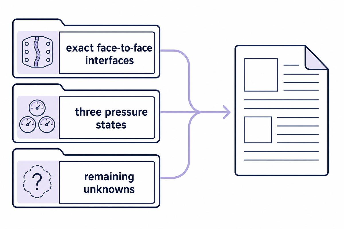
Start the model review only after the application brief identifies the system location, exact face-to-face interfaces, three pressure states, medium and temperature, temporary route, instrument, task procedure, and remaining unknowns. Without current drawings and documented conditions, this guide or a rating calculation cannot support comparison or selection of a specific part.
Once that record is completed, compare the documented hydraulic test point models & connection options on the separate solution page. This single handoff preserves the commercial page’s role; the current guide does not repeat its families, factory statements, warranty, certification, customer, or quotation content.
Key takeaway
A hydraulic diagnostic connection is ready only when present-state permission, complete-chain capability, measurement validity, and evidence handoff are all documented; physical fit or one pressure rating cannot replace any of them.
Frequently Asked Questions
Is a hydraulic test point the same as a test coupling?
Answer
Not exactly. A test point is the installed access interface on the hydraulic system, while a coupling is typically the mating part used to connect a hose, adapter or instrument. Product language varies, so identify the installed side, mating side, seal, thread and pressure-state permission instead of treating the terms as interchangeable.
Does a matching M16x2 thread prove compatibility?
Answer
No. A matching thread can be one necessary detail, but it doesn’t by itself establish sealing geometry, dimensional conformance, rated performance, material or fluid suitability, or permission to connect under pressure. Check current drawings, applicable standard scope and exact manufacturer documentation available before treating two parts as an approved connection.
Can the lowest pressure rating select the correct assembly?
Answer
The lowest documented rating in the proposed chain is an important arithmetic boundary, but it doesn’t select or approve the assembly. Compatibility, pressure while connecting, transient conditions, fluid and temperature limits, routing, calibration and the controlling work procedure still require evidence. Any missing rating remains unknown rather than being replaced by an estimate.
Why might a pressure reading change after connecting a hose?
Answer
The connection can alter trapped volume, introduce gas, expose leakage or restriction, or change the time needed for a reading to stabilize. Treat these as review factors, not universal correction values.
What should a measurement trace contain?
Answer
Record the asset and exact test location; operating mode, load, temperature and time; instrument identifier, range, calibration evidence and configuration; the three pressure states; stabilization behavior, readings, units and repeats; and all uncertainty or unresolved influences. This evidence helps the next reviewer understand what was measured and what the result cannot prove.
Can every pressure test point be used for oil sampling?
Answer
No. Pressure capability does not establish sample representativeness. Use the separate fluid-sampling application guide to assess location, operating state, cleanliness, collection hardware, and the applicable sampling procedure.
Keep the evidence chain intact
Use this guide to define permission, measurement, and record requirements. Use the related product page only after the unknowns have been resolved and current drawings can be checked.
Brand note: IKIN is a registered trademark; TIME Hydraulic is the operating company. This article makes no independent certification, facility, warranty, customer, or universal zero-leakage claim.
References & Sources
- Occupational Safety and Health Administration, 29 CFR 1910.147.
- UK Health and Safety Executive, Hydraulic injection injury safety alert.
- NIST Technical Note 1994, dynamic pressure in a tubing system.
- Fluid Power Journal, Diagnostic Test Equipment case.
- ISO 15171-2:2016 public record.
- ISO 15171-1:1999 public record.
- ASTM D8112-26 public record.
- ISO 4021:1992 public record.
- SAE J1502_202205 public record.