
Get in touch with TIME Company

Hydraulic Test Hose End Fittings — IKIN by TIME Hydraulic
Hydraulic test hose end fittings link a gauge, a sensor or a data recorder to a working hydraulic system without opening a line. Our own plant in Changzhou makes these, together with the microbore test hose and the test point they mate to.
- Quotes back within one business day
- Prototypes in 3 working days
- Up to 630 bar working pressure
- Trial orders from 100 pieces
Test Hose End Fittings at a Glance
Two mistakes account for most of the incorrect parts that arrive in this category: a thread that looks correct and is not, and a pressure figure read from the wrong column. Both follow from the same thing — the connection is specified from two independent ends, and only one shows in a photograph.
Technical Specifications
Working pressure
Up to 630 bar (9,137 psi), rated per part number
Hose bore
DN2 and DN4 microbore assemblies
Connection ends
BSP, NPT, metric, JIC and M16×2
Material
Stainless steel and corrosion-resistant alloys
Trial order
From 100 pieces, your own logo included
Lead time
Prototypes 3 working days, production 10–30 working days
Test Hose End Fitting Types and Connection Styles
Reaching the port at all is decided by the end connection, and it is the part buyers most often get wrong when replacing a lead. Six styles are built as standard, all on the same microbore hose family.
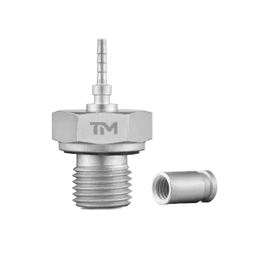
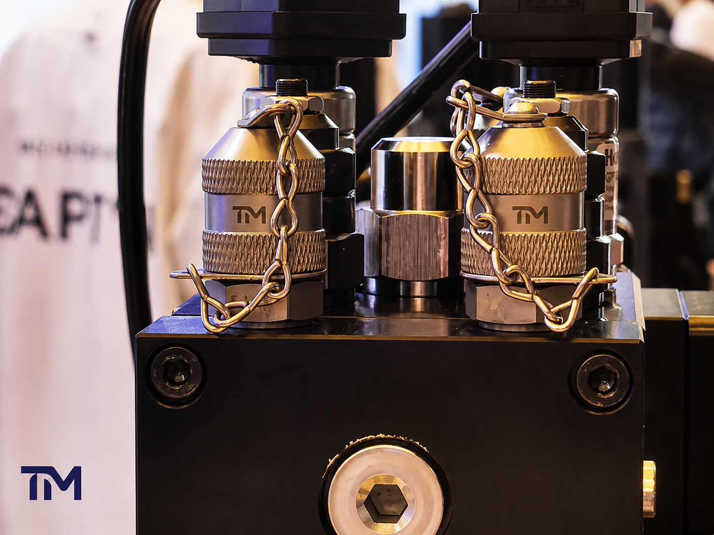
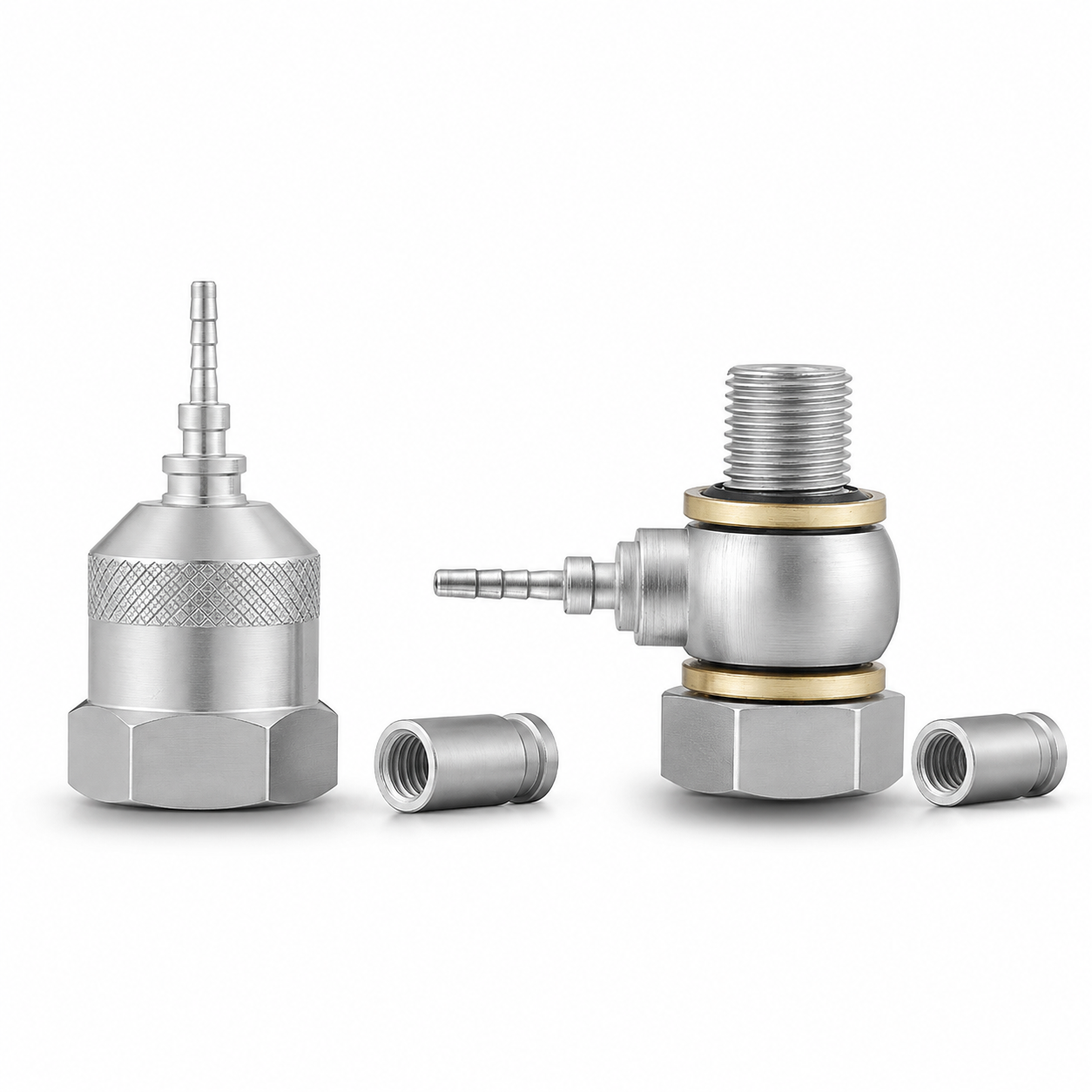
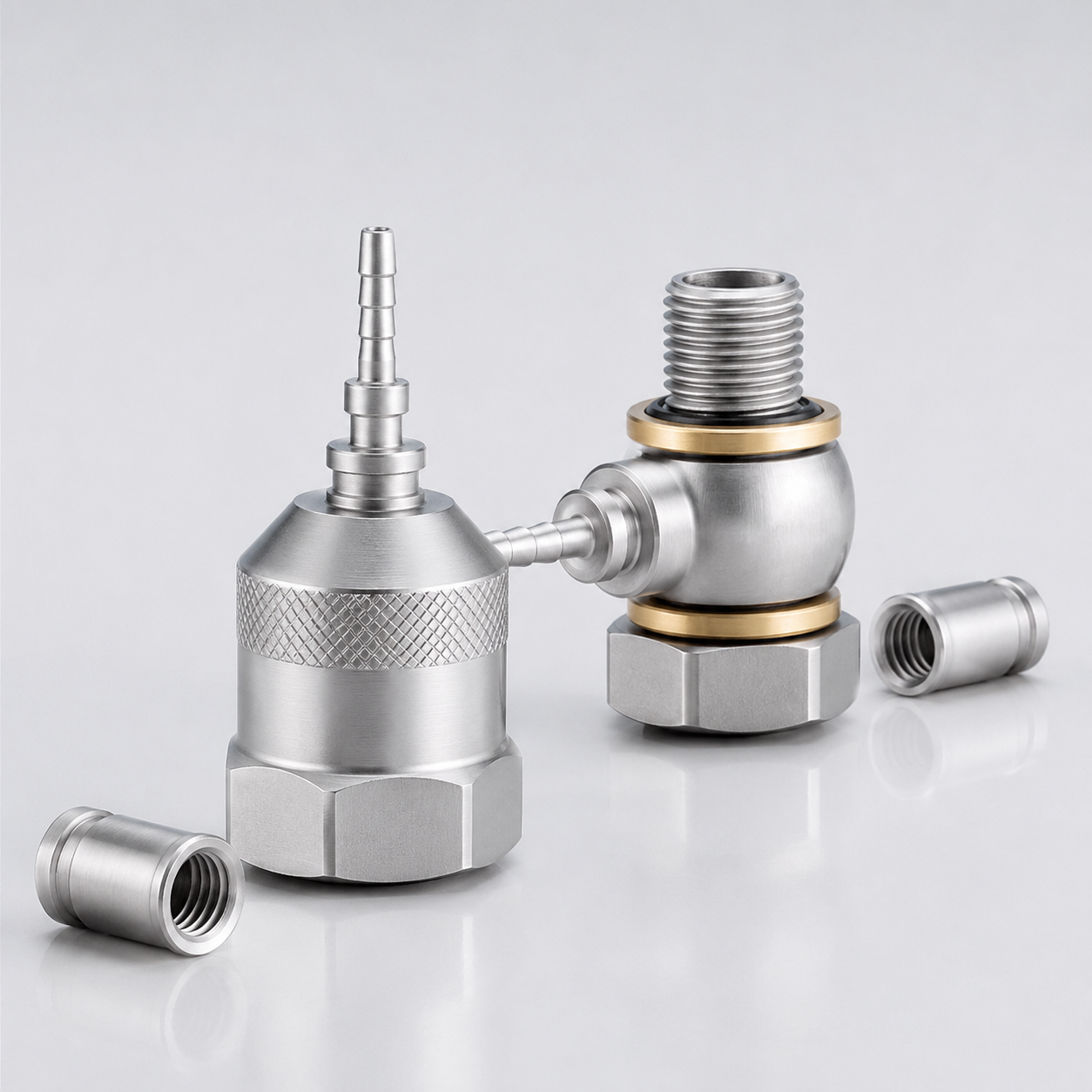
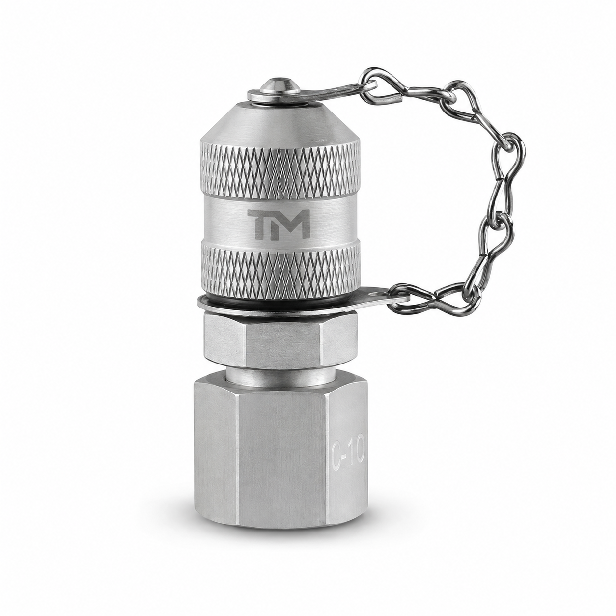
ISO 15171-2 names four port threads for the stud end — ISO 6149-2 and ISO 9974-2 at M14×1.5, ISO 1179-2 at G 1/4, and ISO 11926-2 at 7/16-20 UNF — so the port half is read on its own rather than assumed from the test end. We also produce the diagnostic nipple that stays in the port, so both halves of a measuring position come off a single drawing, each supplied with a protective cap.
| Style | How it mounts and seals | Specify it when |
|---|---|---|
| Male thread with stud connection | A male stud end screws into the port of the machine and presents the diagnostic connection externally | A permanent measuring point is incorporated into a manifold or a valve block |
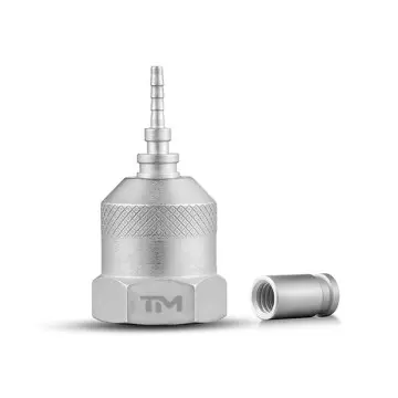
| For test coupling | Mates directly onto an installed test coupling | The machine already has a diagnostic point and only the hose and gauge side is required |
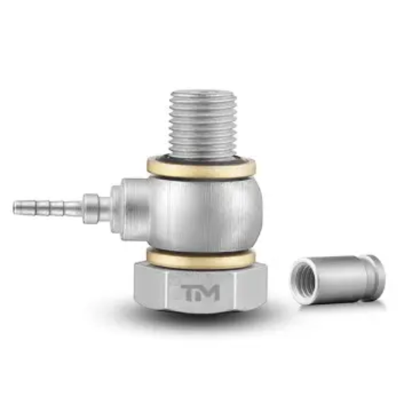
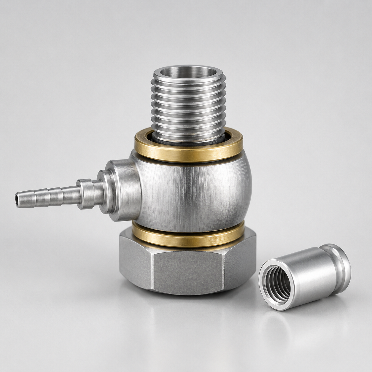
| Banjo connection | A banjo body with a hollow bolt lets the lead leave the port at a predetermined angle | A straight stud end does not have enough space to turn |
| DKO 24° cone seal | A metric 24° cone with a swivel union nut, sealing on the cone face instead of on the thread | The lead has to be routed and tightened without twisting the hose |
| O-ring seal | An elastomer ring carries the seal and the thread carries the load | The connection is broken and remade often enough that a metal seat would suffer damage |
| Direct gauge adaptor | The pressure gauge is fitted straight onto the test connector, with no hose run at all | The port is reachable by hand and only a spot check is needed |
Assemblies leave here completed rather than as loose components: a DN2 or DN4 microbore hose is trimmed, fitted and pressure tested with the connection you specify on each end, and a pressure gauge can be fitted so the lead arrives ready to use.
| Assembly form | End A | End B | Application |
|---|---|---|---|
| Gauge lead | Test coupling connector | Direct gauge adaptor | Portable checks, carried from one machine to the next |
| Sensor lead | Test coupling connector | Male stud or DKO 24° | A transducer or data recorder left in place through a run |
| Point-to-point lead | Male stud | Male stud | Linking two measuring positions on a test rig |
| Angled lead | Banjo | Test coupling connector | Ports inside housings where a straight end cannot turn |
Materials, Seals and Hose Bore Options
Material choice comes down to the fluid the connection sits in and the environment around it. Stainless steel and corrosion-resistant alloys are our standard construction, with the grade confirmed on the drawing and in the quotation: the corrosion resistance sits in the base material, with no coating to wear through at the wrench flats, and austenitic 316-class grades are the usual choice where the fluid or the surrounding air is aggressive. Plated carbon steel is the lower-cost route and is agreed on the drawing when the environment suits it.
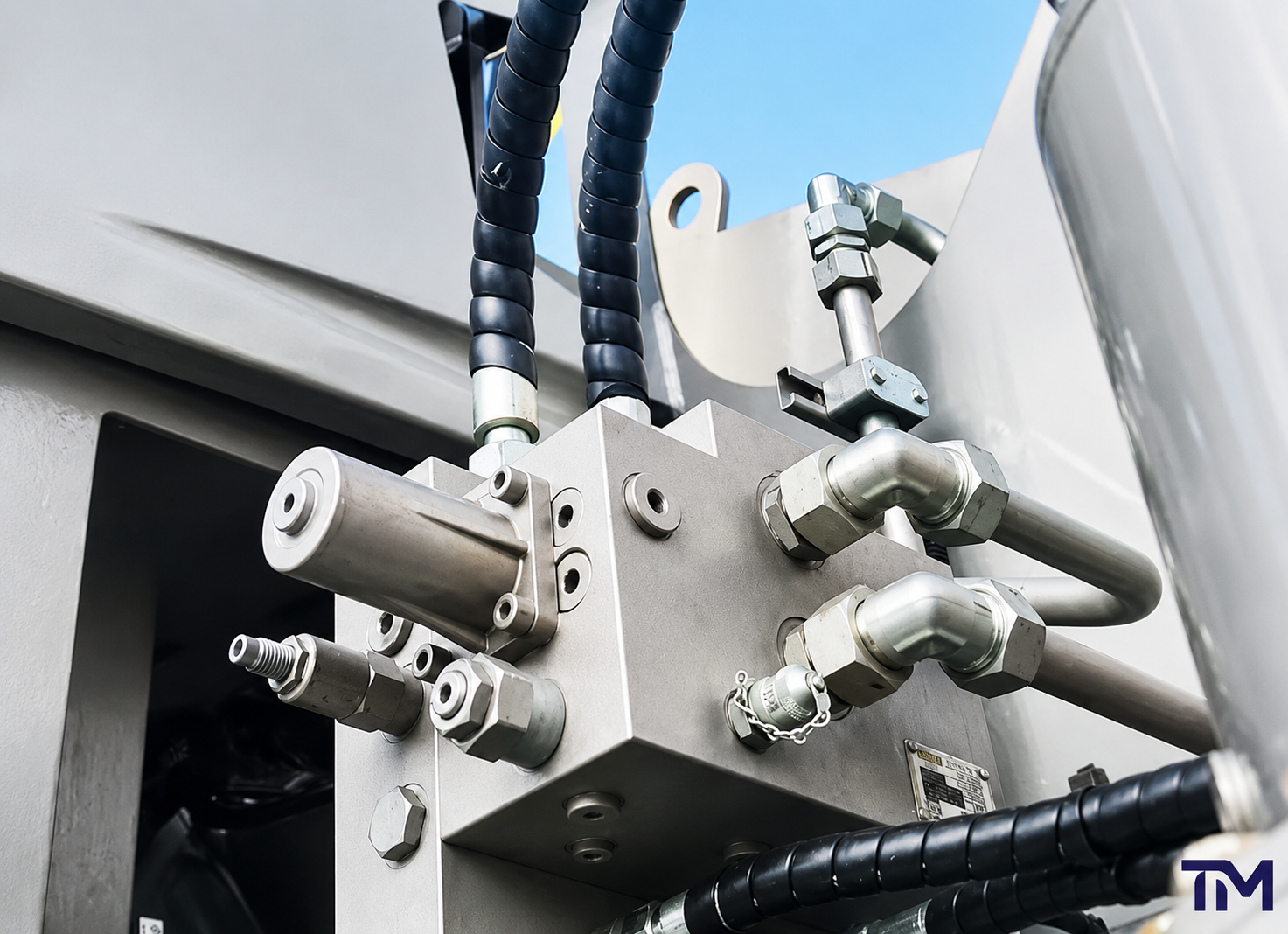
Which seal form a part number carries is set on the drawing, not picked at the counter.
| Seal form | How it seals | Where it fits |
|---|---|---|
| Metal cone seat | Metal-to-metal contact on the 24° cone face, with the union nut supplying the clamping load | Permanent installations, high pressure classes, wide fluid compatibility |
| Elastomer O-ring | A rubber ring carries the seal while the thread carries the load | Connections made and broken often, where a metal seat would mark |
| Poppet seat inside the coupling | A spring-loaded poppet closes the port the moment the lead is pulled off | Any position where the circuit stays live after the gauge comes away |
Microbore is what makes a diagnostic lead readable, since very little fluid has to move before the gauge settles. Bend radius is what you pay for it.
| Bore | Inside diameter | Outside diameter | Minimum bend radius |
|---|---|---|---|
| DN2 | 2 mm (0.079 in) | 5 mm (0.197 in) | 20 mm (0.79 in) |
| DN4 | 4 mm (0.157 in) | 8 mm (0.315 in) | 40 mm (1.57 in) |
NBR covers ordinary mineral oil service, and FKM is specified where the fluid or the temperature calls for it. ISO 15171-2 is written around hydraulic systems running mineral oil and treats any other fluid as something the supplier and the purchaser agree between them, so water-based fluids, phosphate esters and biodegradable oils are confirmed per model before the order is placed.
Check a bore against your own routing. The microbore lead planner takes the tightest radius on your route and the number of corners in it, then says whether DN2 or DN4 clears it and how much hose the run needs.
Access Lead PlannerSurface Treatment and Corrosion Protection
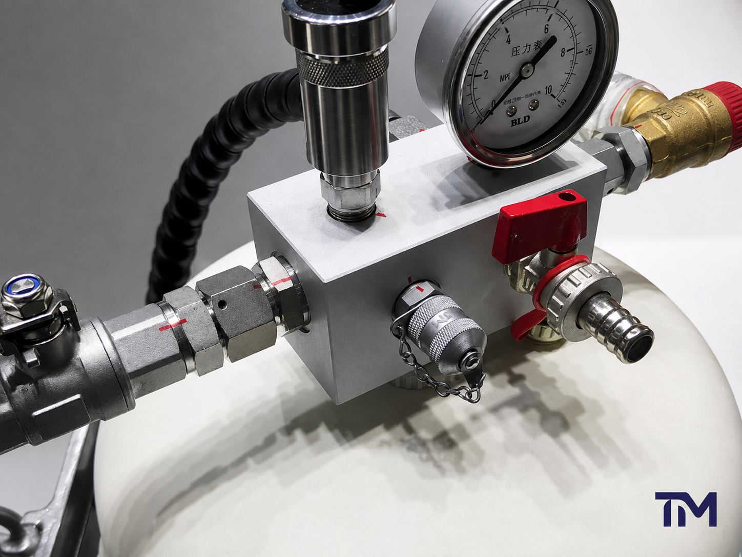
Our standard protection route is the material itself rather than a coating. Where a steel body is specified instead, plating takes over and is agreed on the drawing.
| Protection route | How it works | How it is specified |
|---|---|---|
| Stainless steel construction | Corrosion resistance is in the base material, with nothing to wear through or chip | Material grade stated on the drawing |
| Corrosion-resistant alloy | Same principle, for parts where stainless is not the right mechanical choice | Material grade stated on the drawing |
| Electroplated zinc-nickel, CrVI-free | A sacrificial coating over a steel body — the usual plated route in this product class | Salt spray exposure to ISO 9227 or ASTM B117, cyclic exposure to ISO 16701 |
| Protective cap | Keeps the port closed and dry whenever no lead is connected | Supplied with the machine-side half as standard |
Reading a salt spray number correctly
Salt spray hours are a consistency check on a coating, not a durability score, and ISO 9227:2022 is more candid about that than most datasheets quoting it. The standard specifies the apparatus and the procedure for the neutral, acetic acid and copper-accelerated salt spray tests, hands the exposure period and the interpretation of the result back to the product specification, then states outright that these methods are not intended for ranking materials against each other or for predicting long-term corrosion resistance. So a coating quoted at 480 hours is not worth twice the service life of one quoted at 240, and the protection route for your part number is confirmed on the drawing rather than sold to you as a resistance number.
Specification InquiryIn practice the environment decides this, not the coating datasheet. A stainless body buys you a failure mode that simply does not exist, while a plated steel body costs less at the purchase order and carries the risk that the coating goes first exactly where a spanner lands.
Pressure Ratings, Threads and Dimensions
Two ideas run through this section, and both are places where diagnostic connections get mis-specified.
One M16×2 test end is supplied on small parallel metric threads, on large tapered forms, and on everything between. Published ordering data for this product class shows that one test end rated across several pressure classes purely because the machine-side thread changes, which is why every line in the table below is rated on its own rather than under a single figure at the top.
A diagnostic connection carries two pressure figures, and the lower one governs whenever a gauge goes on a running machine.
That split is written into the standard. ISO 15171-2:2016 describes M16×2 diagnostic couplings that can be connected under pressure without tools to a maximum of 40 MPa (400 bar), while couplings to that part may be used at a maximum working pressure of 63 MPa (630 bar). Compare parts across brands in bar rather than in psi: 400 bar converts to 5,802 psi, yet published imperial equivalents for that same figure differ from one catalogue to the next by around five per cent, which is enough to make two identical connections look like different pressure classes on a purchase order.
Work it out on your own numbers. The pressure figure selector asks for the working pressure of the circuit, whether the lead gets connected while the machine is live, and the two rated limits, then returns the figure that governs and the margin left against it.
Maximum working pressure
Meaning:
What the connection holds once it is made up and stays made up
Where it comes from:
The product specification for that part number; our assemblies are built up to 630 bar (9,137 psi)
Connect-under-pressure limit
Meaning:
The pressure at which the halves may still be joined and parted by hand, without tools
Where it comes from:
Always the lower figure; confirmed per model on the drawing and in the quotation
Pricing, Lead Time and Order Terms
Quoting goes against a drawing or a part number rather than a published price list, because the port thread and the pressure class move the cost more than the quantity does.
Four inputs we need to quote
-
Your machine side
The thread in the port, or the part number stamped on the connection you run now.
-
Your test end required
M16×2, a custom stud end, or what the gauge you already own takes.
-
Your pressure class and fluid
The working pressure of the circuit and what is running through it.
-
Your quantity and marking
Annual usage if you have it, and whether your logo goes on the part.
Our order terms
| Term | Our commitment |
|---|---|
| Quote turnaround | Quotes are returned within one business day, reviewed by an engineer before they go out. |
| Prototype lead time | Prototype parts ship in 3 working days after drawing approval. |
| Production lead time | Production runs are scheduled at 10–30 working days, confirmed with your quotation. |
| Samples | Samples are available and normally dispatched in 3 working days; whether a sample is chargeable depends on the item. |
| Trial orders | Trial orders start from 100 pieces, with your own logo included. |
| Payment | Payment is 30% T/T deposit with the order and 70% T/T balance before delivery. |
| Trade terms | We ship EXW, FOB, CIF and CFR, loading from Shanghai or Ningbo. Trade terms are confirmed per shipment at order stage. |
| Confidentiality | Your drawings and specifications are treated as confidential and protected. |
Turn a working-day figure into a date. The order and stock planner converts the lead time into calendar cover, adds your transit and whatever buffer you keep, and shows where the reorder point lands against your usage.
Manufacturing, Inspection and Warranty
Parts are manufactured and inspected in our own Changzhou plant, which is what lets us hold the records rather than pass on somebody else’s.
On every batch
SPEC-01
We run 100% inspection before packing — every piece rather than a sample drawn from the lot, as our own quality control policy.
SPEC-02
We hold material traceability right through production, and the crimp dimension on hose assemblies sits inside those same records.
SPEC-03
Our product family has passed fatigue testing.
SPEC-04
Products carry a 3-year quality warranty.
SPEC-05
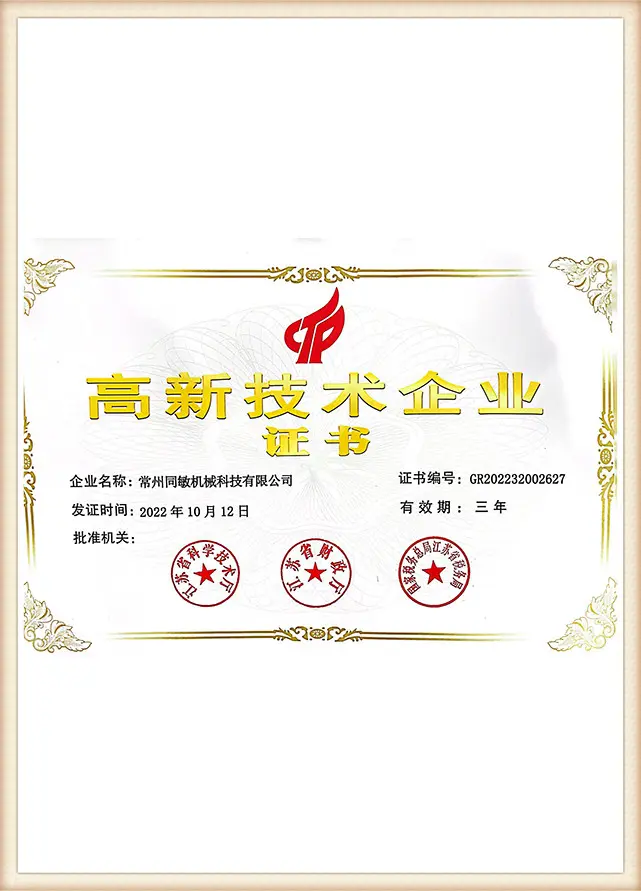
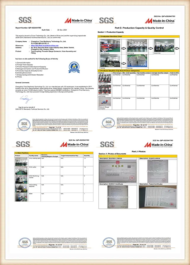
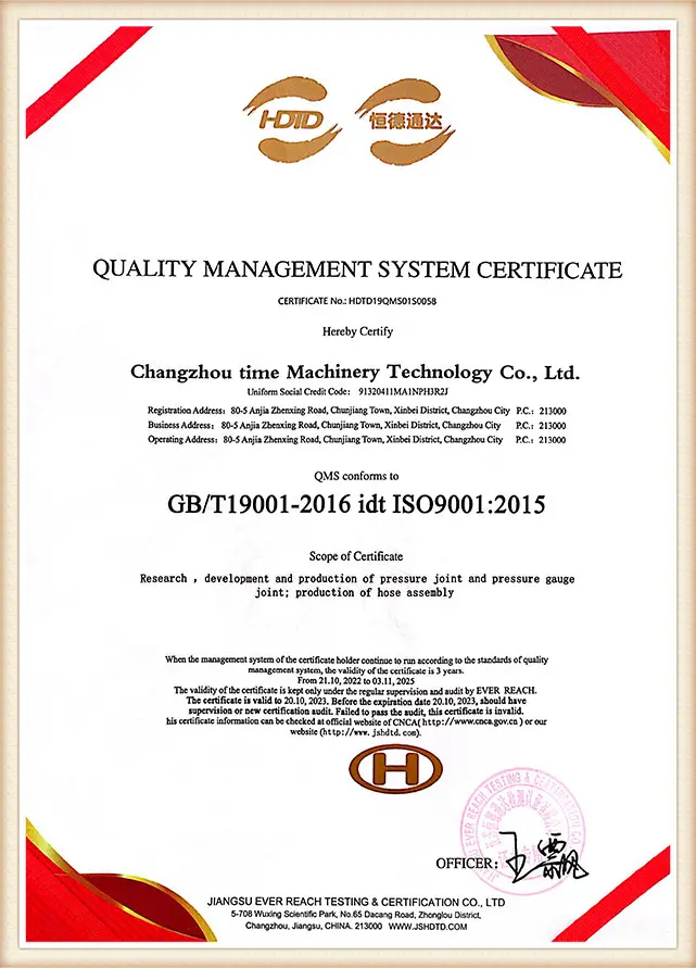
We are ISO approved and SGS approved, and current certificates go out with the quotation whenever your purchasing process needs them on file.
Test-method standards
Test-method standards and acceptance criteria live in different documents, and that is the single most misread thing in this corner of the industry. A burst ratio presented as though a test-method standard demanded it fails the moment somebody opens the document, so we quote the method and the acceptance criteria separately.
Measuring position qualifications
Both halves of a measuring position are qualified under different documents — the quick-action coupling half under ISO 18869, the port and stud-end half under ISO 19879 — so both ends can be individually conforming while the assembly still under-performs, which is why we build and test both halves together.
| Document | Scope | Left to another document |
|---|---|---|
| SAE J343 | Test methods for the SAE 100R hose series | Performance criteria, which sit in SAE J517 |
| ISO 6605 | Uniform test methods for hoses and hose assemblies | Which tests apply and what counts as a pass — the product specification decides |
| ISO 6803 | Impulse testing without flexing, high pressure above 3 MPa and low pressure from 1.5 MPa to 3 MPa | Impulse testing with flexing, which is ISO 6802 |
| ISO 18869 | Test methods for quick-action couplings, each one independent of the others | Which tests to run and the performance requirements — the connector standard decides |
| ISO 19879 | Testing of tube connections, stud ends for ports and flange connections | Coupling-side testing, which is where ISO 18869 applies instead |
| SAE J1502 | Dimensions, performance requirements and test procedures for diagnostic couplers | Rated performance — conformance to the dimensional information alone does not guarantee it |
Notice
Burst testing and proof testing are not the same test
Our assemblies are burst tested to SAE J343 and ISO 6605 methods, with the acceptance criteria taken from the applicable product specification. Rated burst testing is destructive and proof pressure testing is not, so burst is run on samples drawn from the batch while the leakproof proof test is run on the assembly you receive.
How We Work: Cross-Reference and Ordering
Cross-referencing is how this works, and we will not claim general interchangeability with anybody’s system. Compatibility is confirmed against your part number, one connection at a time — which is what a safety regulator expects of a replacement made on a pressurised circuit.
Request quote or drawing review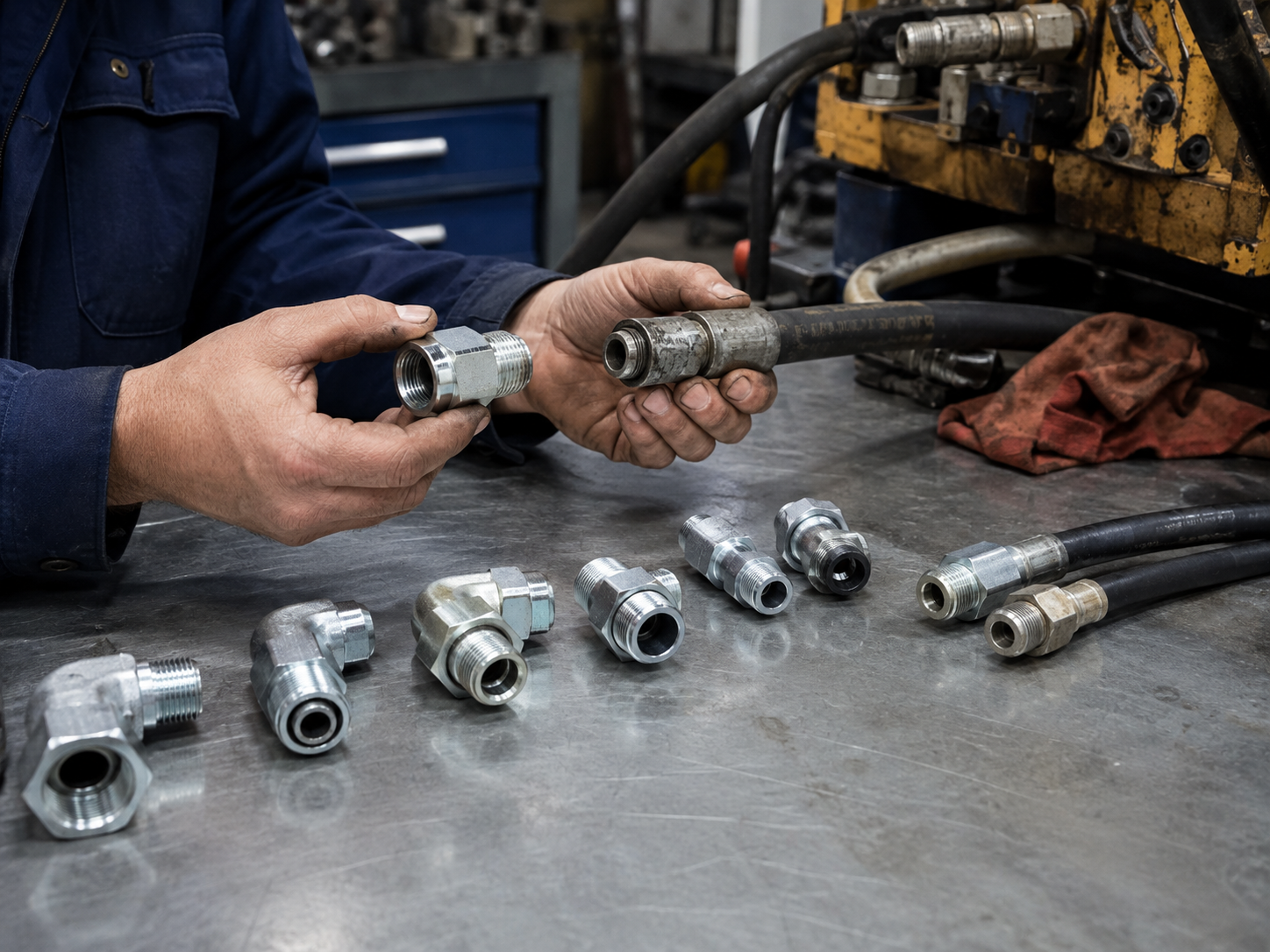
Where replacement or maintenance takes place on a pressurised system, fittings should be matched and compatible as per the original equipment manufacturers specification. Verification of such replacement should be regarded as a pressure test and appropriate precautions taken.
UK Health and Safety Executive, Safety Bulletin FOD 4-2014
-
Start by sending what you have — the part number etched on the existing connection, a drawing, or a clear photograph with a ruler beside it.
-
Both ends are read separately. The port thread on the machine side and the test end on the outside get identified on their own, because they are rated on their own.
-
Compatibility is confirmed part by part — thread family, pressure class and seal form each checked against your own part rather than assumed from the series name.
-
Then comes the quote and drawing review, returned within one business day with an engineer’s comments on anything marginal, followed by a prototype in 3 working days or a 100-piece trial run carrying your own logo.
-
Finally, production, inspection and records. Every piece is inspected before packing and the batch stays traceable.
Selection and cross-reference guide
| Series on your machine | Connection end | Check before ordering |
|---|---|---|
| Minimess 1620 series | M16×2 | The port thread on the machine side, which is rated separately from the test end |
| STAUFF Test 20 series | M16×2 according to ISO 15171-2 | Same test end as above; confirm port thread and pressure class |
| STAUFF Test 15 series | M16×1.5 | Looks like M16×2 and will not mate with it; the pitch differs by 0.5 mm, so confirm it before you order |
| Test 12 series | S12.65×1.5 | A different family; an adapter is needed to reach an M16×2 lead |
| SAE J1502 diagnostic coupler | M14×1.5 or 9/16-18 stud end | A separate standardised family, not a variant of M16×2 |
| Anything else | Read from the stamped part number | Send the number and we confirm the connection end before quoting |
Minimess, MiniPress, Press-Check, EMA and STAUFF Test are trademarks of their respective owners, used here only to identify connections you may already have on the machine.

One interface, six different names
Purchasing loses more time here than engineering does. Test point, Minimess, MiniPress, Test 20, EMA and Press-Check are trade and series names that all land on the same M16×2 diagnostic interface, so a search by name returns six answers while a search by connection end returns one. Send the name you have and the connection end comes back with the quotation.
No legible part number on the machine. The test point identifier takes the thread pitch measured across a counted number of threads, then names the connection end and lists the series that cross-reference to it.
When a measuring position starts to leak
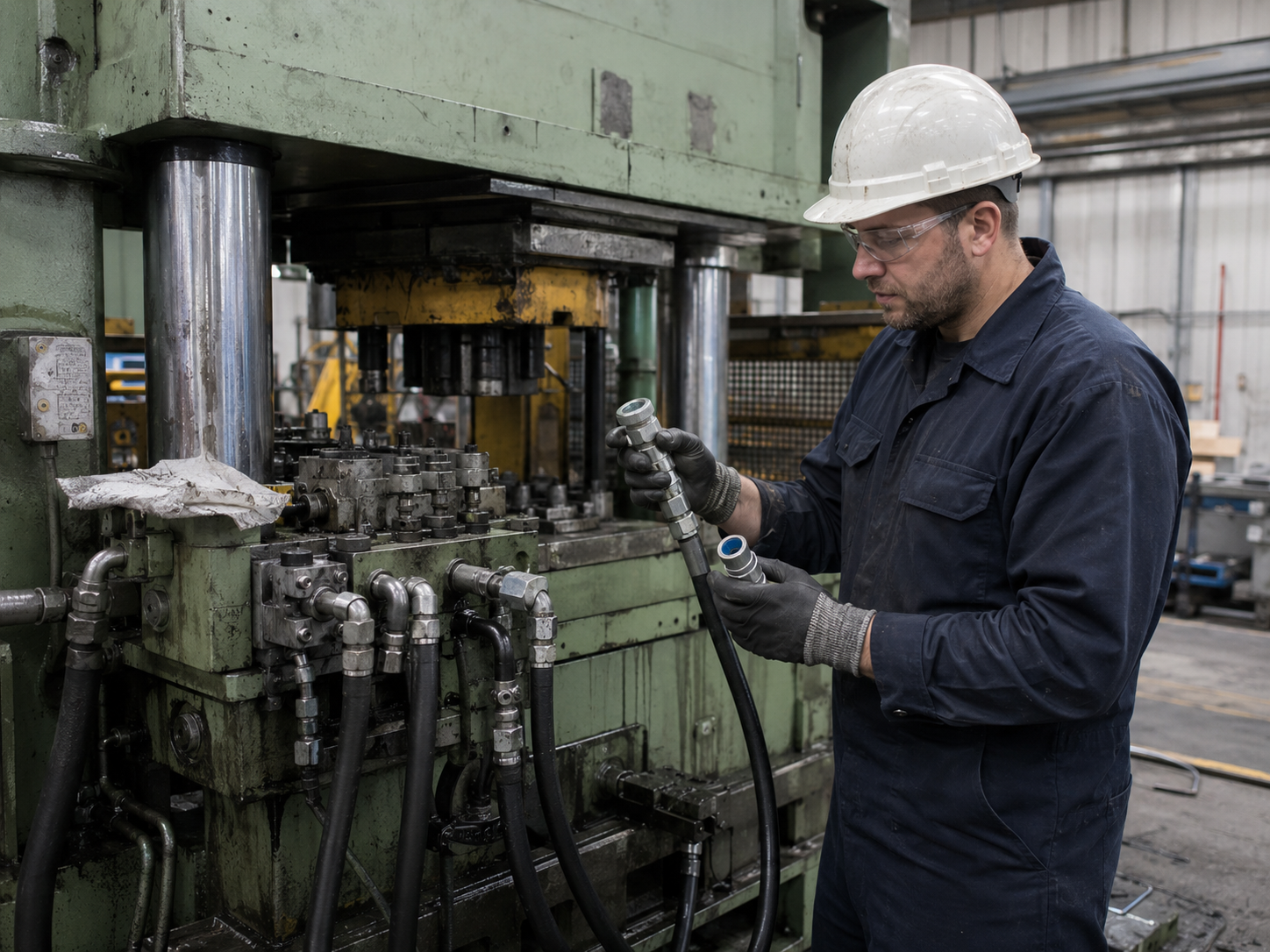
A diagnostic point is connected and disconnected more often than anything else on a circuit, so wear at the coupling face and incorrect tightening account for most leaks reported against this class of part. Tightening torque is not one number either — it moves with the thread family and the seal form inside a single series, so the figure for your part number is issued with the drawing.
Applications and Equipment Compatibility
Diagnostic connections are specified by interface family and pressure class, not by the badge on the machine — which keeps a purchase order from going out against a brand name that covers three incompatible systems.
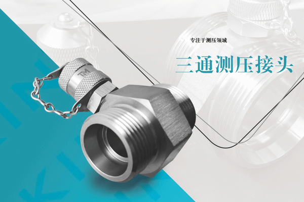
| Family | Connection end | Connection under pressure | Pressure figure in that document |
|---|---|---|---|
| ISO 15171-2:2016 | M16×2 | Connectable under pressure without tools, to a maximum of 40 MPa (400 bar) | Usable at a maximum working pressure of 63 MPa (630 bar) |
| ISO 15171-1:1999 | Male diagnostic coupling | Not intended for connection under pressure | Written for connections made with the circuit shut down |
| SAE J1502 | M14×1.5 or 9/16-18 straight thread stud end | Not stated in the same terms | May be used at a working pressure of 42 MPa |
Each row carries the figures from its own document and they are not comparable across rows, because the documents define them under different conditions. SAE J1502 also bounds its scope to machines within the categories of SAE J1116: earthmoving, forestry, road building, specialised mining and powered industrial trucks.
Construction and cranes
Excavators, cranes and other heavy equipment, read at commissioning and again at service intervals
Wind power
Pitch and yaw hydraulics, the sector our own test connection development started in
Agriculture and forestry
Tractor and harvester circuits
Industrial automation
Presses, clamping circuits and power units on the factory floor
Power generation and rail
Turbine auxiliaries and rail vehicle hydraulics, where records matter as much as readings
Injection moulding
Clamp and injection circuits, checked against pressure profiles
Who we supply and how we got here
Companies we have supplied include SANY, XCMG, Zoomlion, CRRC, Hengli, Caterpillar, Parker, HAWE, Bucher and Argorhytos. TIME Hydraulic began in 2009, moved to its own development work in 2014 by entering through wind power, and built the Changzhou plant in 2017 on a 5,000 square metre site. Since then the range has stayed narrow on purpose: diagnostic connections, microbore test hose and the ends between them are what we make, and we have not widened into general hydraulic hardware.
Ask our engineer a questionWhere a Test Hose End Fitting Is Not the Right Choice
CONSTRAINT 01
Same-day breakdown cover.
Our model is production and shipment from Changzhou, not next-day delivery off a local shelf. With a machine down this morning we are the wrong answer, and a local distributor is where to look instead — then use us behind that, sizing a safety stock against your annual usage.
CONSTRAINT 02
A permanent branch in the line.
A microbore lead is built to be connected, read and taken off again. Where a line is clamped down permanently and lives with constant vibration, a flexible lead is the wrong choice and a fixed tube run with a run tee outlasts it — the leads that come back as hose failures are the ones left hanging on a machine for months.
CONSTRAINT 03
Connecting above the rated limit.
If a procedure calls for a gauge to go on while the circuit sits above the connect-under-pressure limit, no connection style makes that safe and the circuit has to come down first.
Hydraulic Test Hose End Fittings Engineering Tools
Pressure Figure Selector
Determine the precise pressure rating requirements for your hydraulic systems. Select the right end fittings based on operational parameters.
Access Selector Tool
Test Point Identifier
Accurately identify test point threads and sealing types. Ensure seamless integration with Stauff, Minimess, or MCS diagnostic systems.
Open Identifier Tool
Microbore Lead Planner
Calculate the optimal length and routing for microbore hose assemblies to minimize pressure drop and optimize fluid diagnostics.
Start Lead Planner
Order and Stock Planner
Manage your inventory and OEM procurement schedules. Streamline your MRO and bulk replacement ordering process accurately.
Run Stock Planner
Resources
Frequently Asked Questions
What are the different types of hydraulic test ports?
They divide by two things at once: the connection presented on the outside and the port thread on the inside. On the outside, M16×2 to ISO 15171-2 is the most widely published family, while SAE J1502 defines a separate diagnostic coupler with an M14×1.5 or 9/16-18 stud end. On the inside, that same outside connection is supplied with BSPP, NPT, metric, JIC and UNF threads, which is why two parts that look identical do not always suit the same machine.
Is a slow weep at a test point something to live with?
No — treat it as a fault, even though a slight seep at a diagnostic connection is often tolerated until something else forces the issue. Wear at the sealing face is the first thing to look at, since this connection is opened and closed more often than anything else on the circuit and a scratch across the poppet seat passes fluid where a gauge port never should; tightening comes next, because a stud end pulled up past its torque distorts the same seat it is meant to seal against and one left short of it never seats at all. Send us the part number and a replacement comes back matched on both ends.
Can I order a trial quantity with my own logo?
Yes. Trial orders start from 100 pieces and your logo is included at no extra charge. We keep the marking artwork with the drawing, so a repeat order carries the same marking without you sending it again.
What are your lead times and payment terms?
Prototypes ship in 3 working days after drawing approval and production runs at 10–30 working days, confirmed with your quotation. Payment is 30% T/T deposit with the order and 70% T/T balance before delivery, on EXW, FOB, CIF or CFR terms out of Shanghai or Ningbo.
What certifications does TIME Hydraulic hold?
We are ISO approved and SGS approved, and current certificates go out with the quotation when your purchasing process needs them on file. Every piece is inspected before it is packed and materials stay traceable through production. Products carry a 3-year quality warranty.
