
Get in touch with TIME Company

Test Connections for Mining & Rock Drilling
Test Connections for Mining & Rock Drilling should help a technician reach a known circuit with the right port interface, pressure class, hose route and gauge connection. TIME Hydraulic supplies the connection hardware; the machine manual, site isolation rules and a model drawing still govern the job.
Requirements & Scope
Core Parameters
- Drawing-led connection review
- Model-bound material options
- Pressure, flow and temperature boundaries
Three buyer-side constraints
- A pre-packed kit can still omit the machine-specific adapter that stops the job.
- Pilot, implement and main circuits can need different gauge ranges.
- Hose reach is a selection input because the test port and the safe observation position can be far apart.
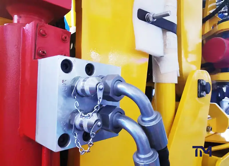
Send the machine make, measurement location, port evidence and pressure-test range. We narrow the discussion to one connection chain rather than treating a mining truck hydraulic test coupling as a universal adapter.
01
Start at the machine
Record the port, thread form, sealing face and test location before choosing the hose or gauge end.
02
Rate the whole chain
The port, coupling, hose, adapter and instrument are checked against the lowest working-pressure rating in the assembled path.
03
Match the fault
Pressure answers one question. Slow cycle, heat or efficiency symptoms can require flow or temperature measurement as well.
Hydraulic Test Points, Couplings, and Hoses for Mining Trucks and Rock Drills
For selection support, review hydraulic test hoses and fittings when the specified connection family matches the drawing and operating conditions.
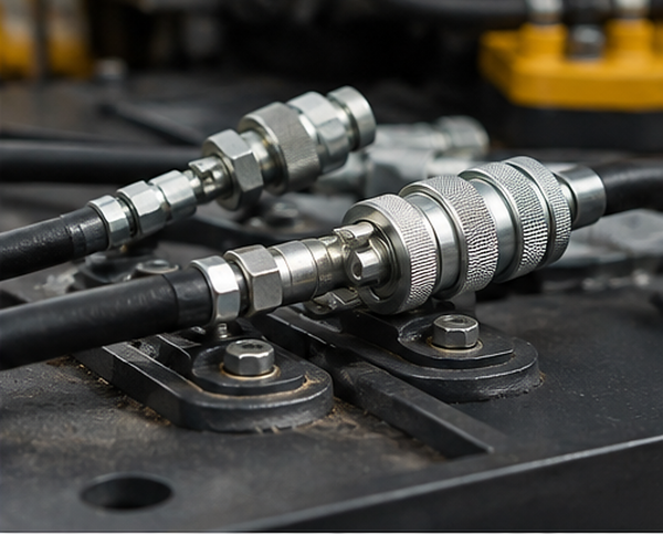
We manufacture hydraulic test points and test hoses for pressure access on mining trucks and hydraulic rock drills, including detachable diagnostic couplings, remote test hoses and gauge or transducer interfaces. “Rock drill test hose” here means a hydraulic diagnostic hose. It does not mean a pneumatic drill air-supply hose.
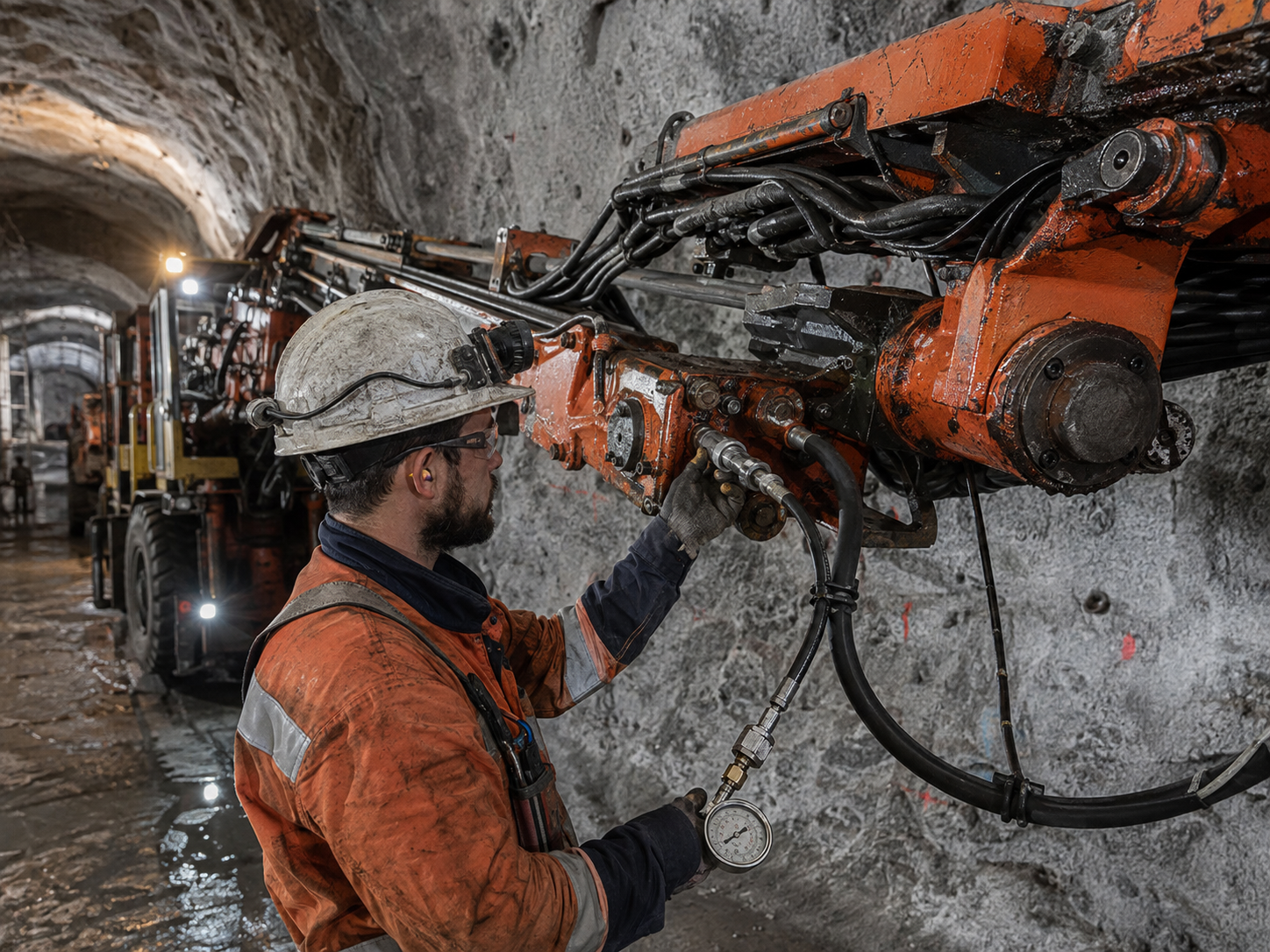
Machine-side test points
Our range includes hydraulic test points for diagnostic pressure access. Port geometry and the sealing method are confirmed from the drawing or measured connection, because a thread that turns in is not proof that the seal is correct.
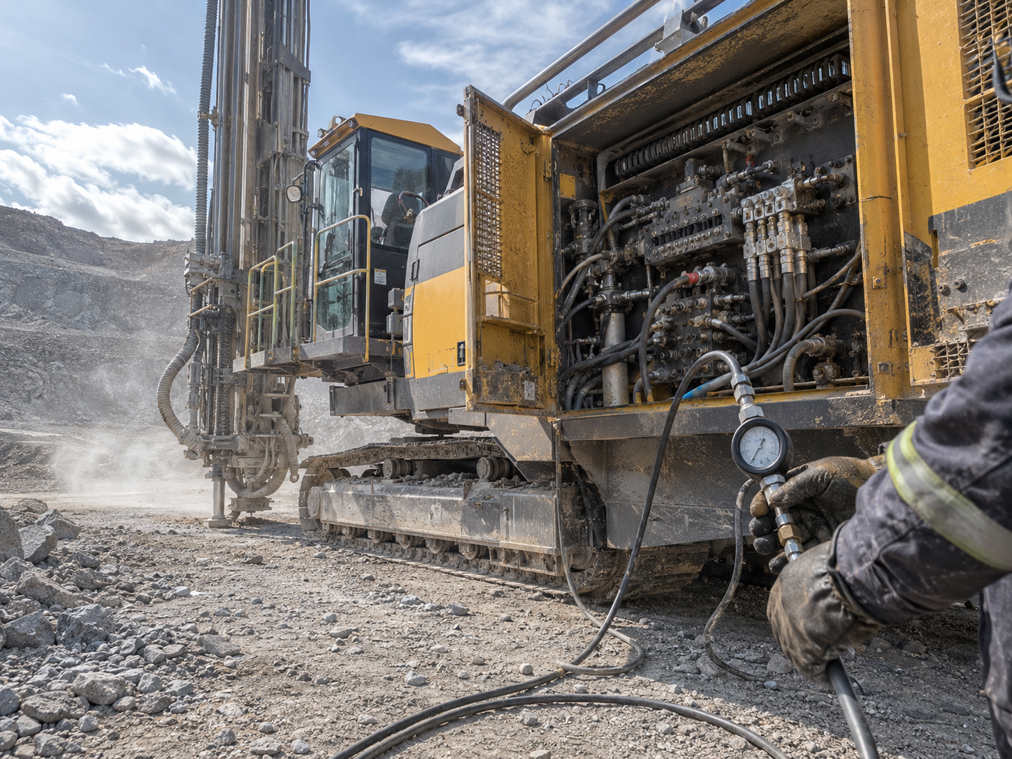
Diagnostic couplings
ISO 15171-2 defines an M16 × 2 interface for diagnostic coupling use. Treat it as a standards reference only; request a current TIME model drawing, then compare the thread geometry, sealing face, pressure rating, fluid and temperature before assuming it matches the machine-side port.1
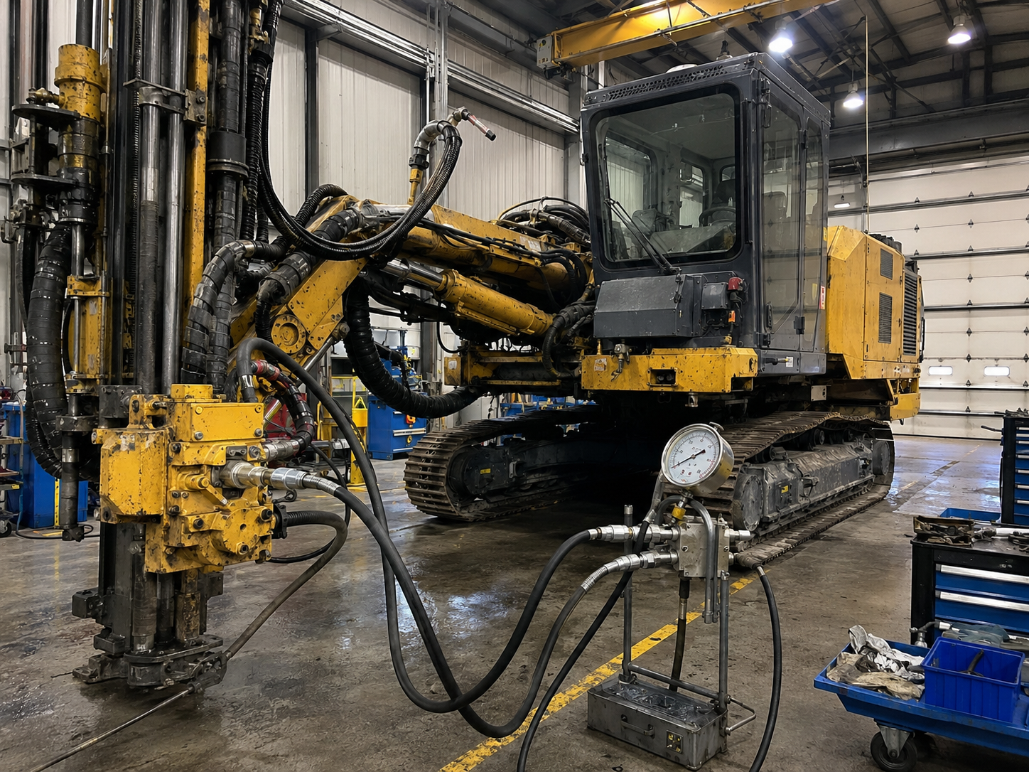
Remote test hoses
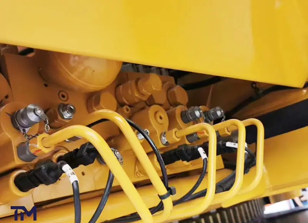
Our range includes hydraulic test hoses for remote gauge and transducer connections. Hose length is selected around reach, observation position and the route, not by taking the longest hose on the shelf.
Connection-chain review
The port evidence includes the machine model, circuit position, thread diameter and pitch, taper or parallel style, and the sealing face.
Interface evidence separates an SAE or JIC family label from actual geometry; record whether an O-ring, cone seat or another seal carries pressure in the hydraulic system.
Pressure information covers circuit working pressure, pressure during mating and the rating of every downstream component.
Hydraulic fluid, temperature range and desired seal and body material are provided in media evidence.
Measurement information describes the required gauge or transducer interface, full scale, accuracy requirements and fault symptom being diagnosed.
A coupling with a high printed rating cannot raise the rating of the hose, adapter, gauge or low-rated fitting beside it. Selection starts with the weakest entered component and ends with drawing confirmation.
Transparency
The honest selection boundary
The honest version is that TIME Hydraulic will not claim universal fit from a product family name. A thread label is not automatically a sealing match, and the trade-off for a drawing-led review is a little more input before the quote but far less guessing at the machine.
Connection Materials and Seal Choices
When choosing a material for service, start by looking at the actual fluid, temperature, corrosion exposure and mating connection. Do not rely upon the name of a material to determine compatibility or lifespan.
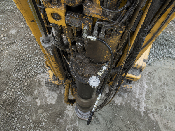
Stainless-steel options
- We offer stainless-steel test-point options by model.
- Our referenced stainless-steel range includes 304 options.
- Our referenced stainless-steel range includes 316L options.
- Use the drawing review to tie grade, geometry and seal to the requested model.
- Do not infer salt, chemical or temperature suitability from the word “stainless” alone.
Carbon-steel options
- We offer carbon-steel connection options by model.
- Carbon steel can be a practical choice where the service environment, coating and maintenance plan are defined.
- Confirm coating callout and exposed surfaces.
- Keep the machine-side seat and seal form separate from the body material decision.
- Request the exact model drawing before replacing a stainless connection with carbon steel.
Seal and fluid review
- Our referenced model range includes NBR, FKM, EPDM and low-temperature seal options. Those names create a shortlist; the fluid formulation, additives, temperature and storage conditions decide which option should be quoted.
- ISO 15171-2 is written for mineral-oil-based fluids; other fluids require agreement between supplier and purchaser.1
- Name water-glycol, biodegradable and fire-resistant fluids in the request instead of grouping them as “hydraulic oil.”
- Where the machine operates from cold-start up to its operational high temperature, submit both limits, as opposed to sending an ambient value alone.
Material mismatch check
A wrong seal or body choice raises leakage and contamination risk because fluid chemistry and temperature change the service demand.
Coatings, Hose Protection, and Mine-Site Routing
Our referenced carbon-steel range includes zinc and zinc-nickel coating options. The coating choice belongs on the model drawing, while hose protection belongs in the route review.
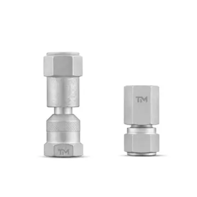
Abrasion and pinch points
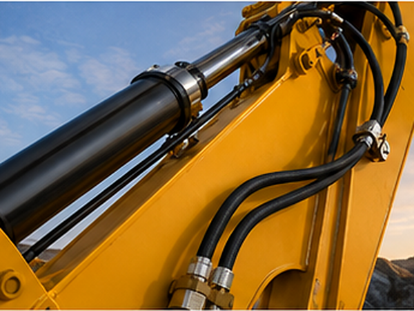
Look for frame edges, clamps, guards and moving structures that can rub or trap the hose. A sleeve can help with exposure, but it does not correct a route that is forced across a sharp edge.
Bend behind the coupling
A tight bend directly behind the end connection transfers load into the hose and fitting. Give the route enough freedom for machine movement without letting the hose enter a crush zone.
Heat and technician position
Keep the route clear of exhaust, hot surfaces and unguarded moving parts. Set reach so the technician can read the instrument from the intended position without pulling the hose taut.
Why routing belongs in the RFQ
One mine fatality report described a hose and fitting failure after improper support imposed bending load; the released assembly could whip.6 The incident is not a product comparison, but it shows why hose length, support and worker position cannot be treated as packaging details.
Machine-Side Ports, Pressure Classes, and Test-Hose Configurations
Pressure appears at more than one point, and the numbers can refer to different limits. Connection-under-pressure scope, maximum working pressure, proof testing and the lowest working limit of the built chain have to remain separate.
| Decision item | Number or standard | How to use it |
|---|---|---|
| Diagnostic interface in ISO 15171-2 | M16 × 2 | Confirm that the installed port and sealing details match the intended model; do not select from thread label alone. |
| Connection under pressure within ISO 15171-2 scope | Up to 40 MPa / 400 bar | This is a coupling-standard boundary, not an instruction to connect a particular machine while pressurized.1 |
| Conditional maximum working pressure in ISO 15171-2 | Up to 63 MPa / 630 bar | The standard makes this dependent on materials, design, working conditions and application.1 |
| Model-specific working pressure | Confirm on current drawing | Use the lowest confirmed rating across the connection, hose, adapter and instrument. |
| Model-specific body and seal materials | Confirm on current drawing | State the fluid, temperature and exposure; do not infer compatibility from a family name. |
| Hose and hose-assembly test-method scope | ISO 6605:2017 | Use the applicable product specification to set acceptance criteria; the method title alone is not a certificate for a TIME model.2 |
| Hydrostatic test-method scope | ISO 1402:2021 | Use it to frame requested hydrostatic and dimensional-stability evidence for a hose assembly.3 |
| Steady-state pressure measurement scope | ISO 9110-2:2020 | Define the measurement boundary and uncertainty needed for the diagnostic decision.4 |
| Client-confirmed sample arrangement | Within 3 days | Use the sample to verify drawing, fit and requested records before a larger order. |
Lowest-rated component check
An MSHA investigation indicated that an 800 psi-rated brass fitting was exposed to a 3,000 psi hydraulic circuit. The fitting burst and launched the attached sensor.5 The purchasing lesson is to record every rating in the chain and compare the circuit with the lowest one.
Known M16 × 2 port
Check the standard scope, pressure during connection, body and seal option, then match the test hose and instrument end. The route still ends in model confirmation.
Unknown or mixed port family
Send a port photo with scale, thread diameter, pitch, taper or parallel form, sealing face and machine drawing reference. A near-looking adapter is not a fit decision.
RFQ Inputs, Samples, and Lead Time Confirmation
Price is based on the machine-side connection, body and seal material, hose length, end interfaces, quantity and requested document set. We do not convert a pressure value into a price until the other parts of the connection chain are defined.
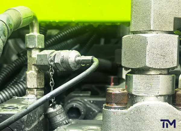
Inputs that shorten the quote loop
| Input | What to send | Why it matters |
|---|---|---|
| Machine identity | Make, model, serial range and test location | Separates a general product request from a machine-side application. |
| Port evidence | Drawing, port callout, measured thread and sealing-face photo | Reduces false matches between similar-looking threads. |
| Pressure chain | Working pressure, connection pressure and ratings for hose, adapter and instrument | Exposes the lowest-rated point before a model is quoted. |
| Fluid and temperature | Fluid name or formulation plus minimum and maximum temperature | Controls the seal and material shortlist. |
| Hose route | Measured reach, bends, heat, abrasion, support and operator position | Turns “long enough” into a reviewable route. |
| Delivery scope | Quantity, sample need, drawings and requested inspection records | Keeps the commercial quote aligned with the evidence package. |
Send the data sheet
Unknown fields remain marked for confirmation.
Review connection drawing
The model and ends are tied to the stated machine-side evidence.
Arrange the sample
Samples can be arranged within 3 days.
Confirm order schedule
Production and shipment timing are set after configuration, quantity and commercial terms are agreed.
This page does not publish an unverified price, minimum order quantity or production lead time. The written quote becomes the transaction record for the chosen configuration.
Create the Mining Circuit Evidence RecordInspection, Test Evidence, and Traceability
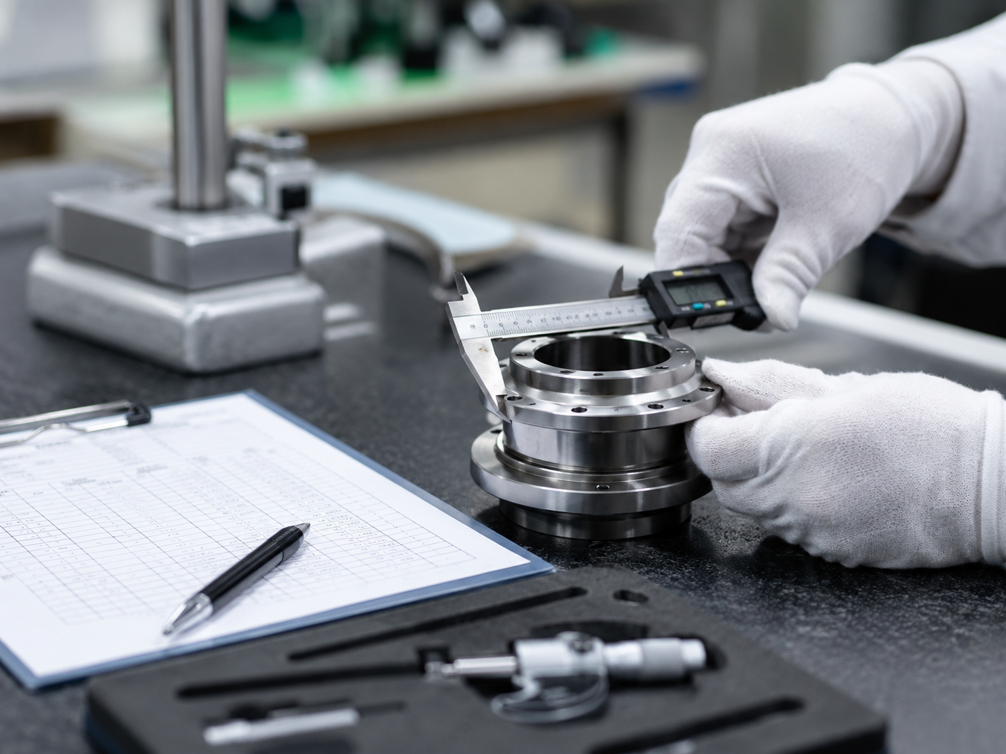
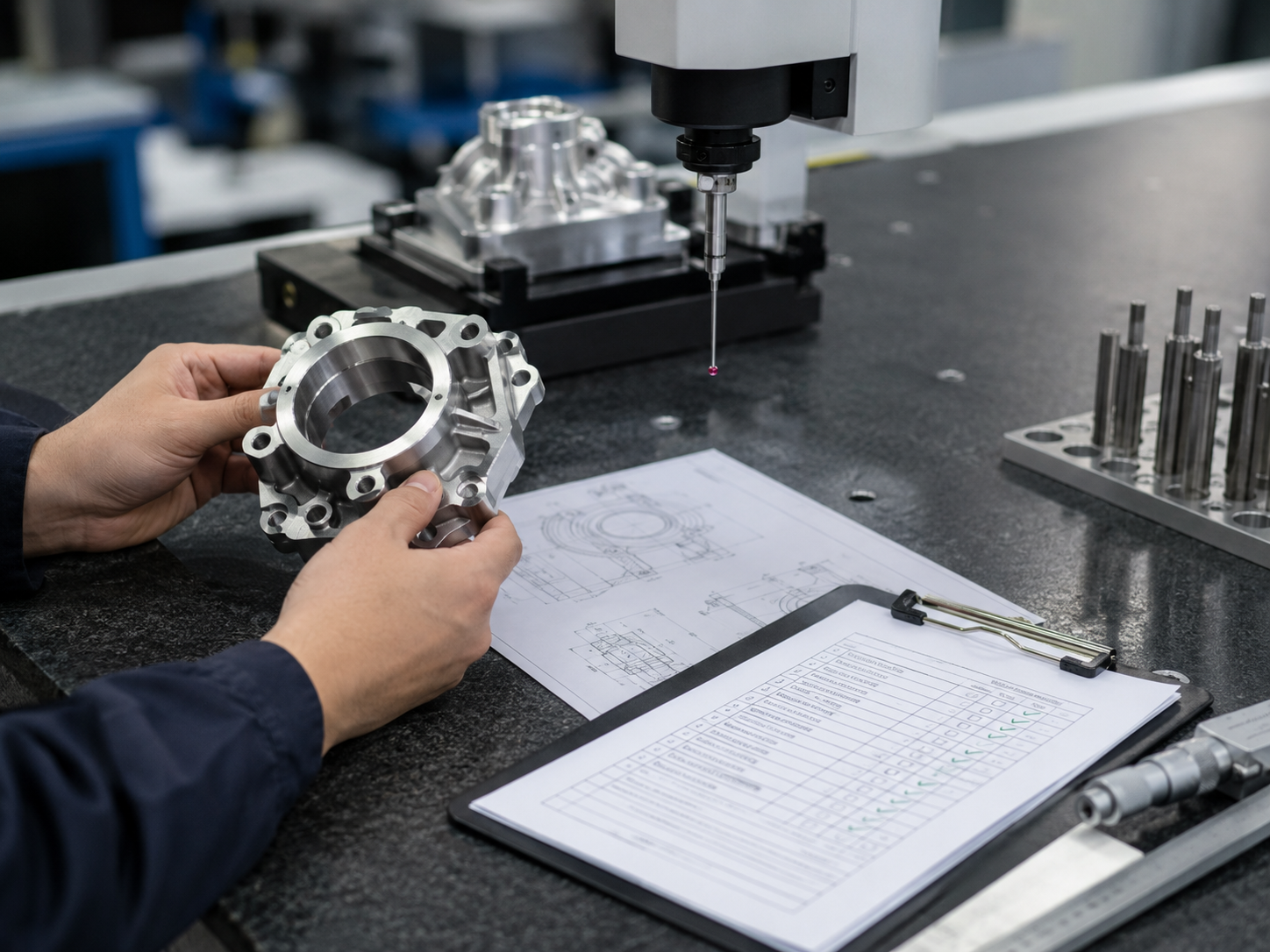
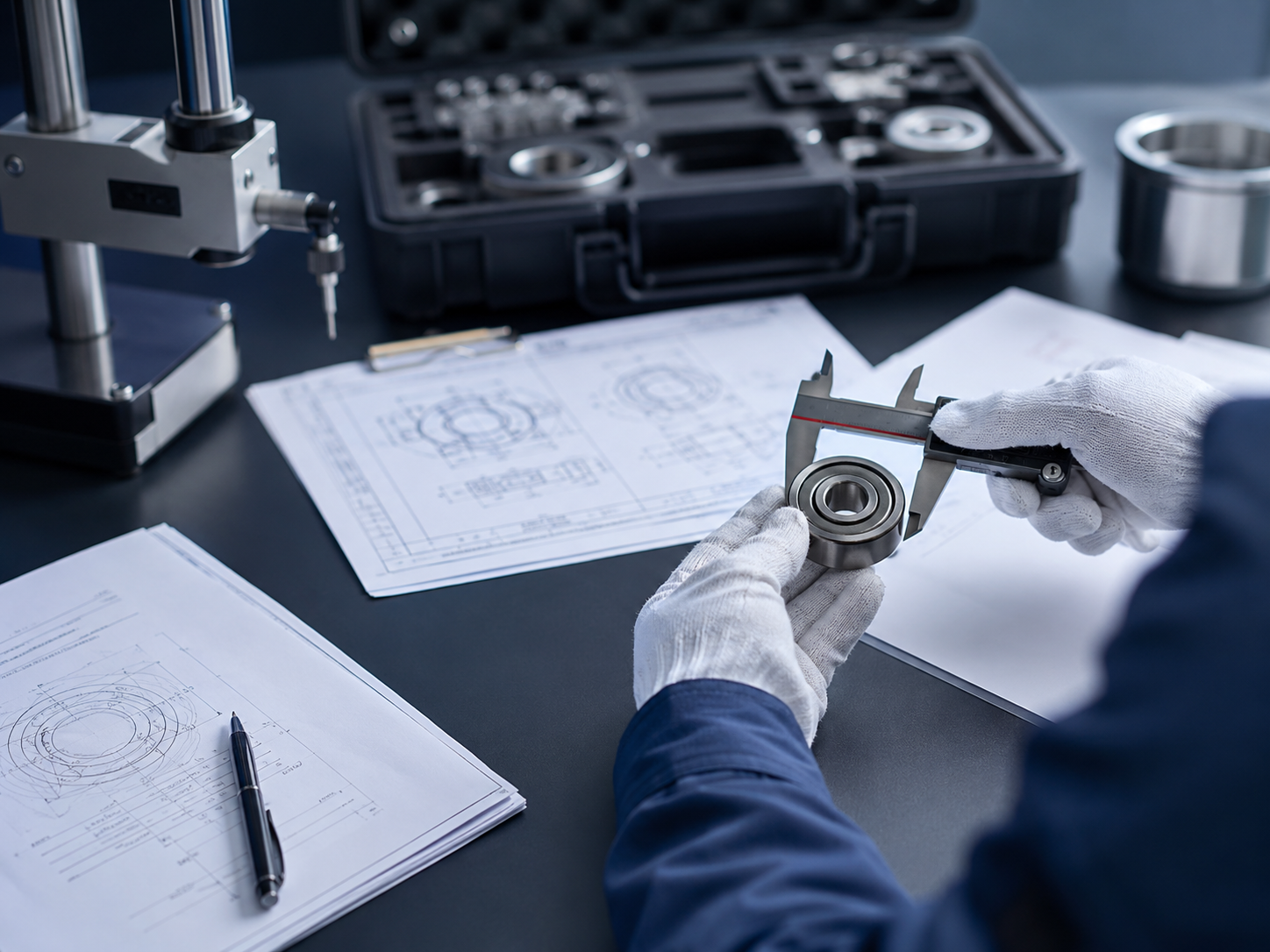
A useful quality package links the purchased model to its drawing, acceptance criteria and the records named in the order. The risk of mismatch remains because a standard test method is not the same as a product-compliance claim, so each record must identify the model and criteria.



Written quote boundary
TIME Hydraulic manufactures hydraulic test points and hoses, while the RFQ defines the ordered model. State the inspection scope, inspection records and model drawing as order requirements, not assumed deliverables, until they appear in the written quote.
Six-Step Connection Review
The review turns machine evidence into an ordered connection chain. Each step produces a defined output, so a missing field stays visible rather than receiving an assumed value.
-
STEP 01Define the diagnostic question
State whether the job concerns steady pressure, slow movement, heat, drift or another symptom.
-
STEP 02Confirm the test position
Provide the machine model, circuit identifier and the OEM drawing or service reference available to the technician.
-
STEP 03Identify the port
Document thread form, diameter, pitch, sealing face and a scaled photograph when the drawing is incomplete.
-
STEP 04Construct the pressure chain
List circuit, connection, hose, adapter and instrument ratings, then find the lowest value.
-
STEP 05Check media and path
Add fluid, temperature, body and seal selection, hose reach, bends, heat, abrasion and support.
-
STEP 06Freeze the quoted configuration
Approve the model drawing, sample scope, quantity and requested records before agreeing production timing.
Pressure is not the whole diagnostic
A pressure reading alone could mask a flow-loss problem. Whenever slow movement or output loss becomes a symptom, incorporate flow readings and a cycle-time test into the diagnostic plan.
Path Link Active
-
Pressure path
Use a gauge or pressure transducer when the question concerns a defined pressure point and a steady-state value.
-
Flow path
Add flow measurement when pressure is present but actuator speed, pump output or cycle time has changed.
-
Temperature path
Add temperature measurement when heat rise, viscosity change or a location-specific thermal condition is part of the fault.
Diagnostic-value card
Fewer blind assumptionsValue comes from reducing wrong adapters, incomplete gauge kits and repeated RFQ exchanges. No client-specific savings percentage or payback period is claimed.
Selection Limits and Safer Alternatives
A hydraulic pressure test connection is only useful when the port, pressure chain, route and diagnostic aim are defined. These limits prevent the page from turning a component guide into operating instructions.
| Situation | Why it works against the job | Better next step |
|---|---|---|
| The machine-side port is unknown | A matching diameter can hide a different pitch, taper or sealing face; forcing the connection risks damage and leakage. | Measure the thread, photograph the seat with scale and request a drawing review.7 |
| The equipment cannot be isolated under the site procedure | A component page cannot authorize connection to stored hydraulic energy or replace the OEM and mine safety process. | Stop and follow the machine manual, competent-person decision and site isolation rules. |
| A downstream item has no rating | The highest-rated coupling does not compensate for an unknown hose, adapter or instrument limit. | Identify every component and select against the lowest verified rating. |
| The symptom is slow cycle or lost output | Correct pressure can coexist with reduced flow, so a pressure-only kit can miss the fault. | Add the required flow measurement and compare it with the machine’s service criteria. |
| The hose route crosses heat, abrasion or movement | Reach alone does not address bend load, pinch points, surface damage or hose whip exposure. | Revise the route, support and protection plan before requesting the final hose build. |
| The fluid or temperature is not known | Seal and material labels cannot be assessed without the actual media and temperature band. | Collect the fluid specification and both temperature limits before choosing the model. |
Test Connections for Mining & Rock Drilling
Machine to Gauge Data Sheet
Generate exact parameter matches between heavy machinery diagnostics and standard gauge specifications. Ensure accurate pressure readings in harsh mining conditions.
Open Tool
Test Connection Selection Matrix
Filter and select the precise test point based on working pressure, thread size, and sealing type for your rock drill applications.
Open Tool
Test Hose Routing Review
Evaluate proposed hose paths for mechanical exposure and bend radius constraints. Prevent premature failure in abrasive mining environments.
Open Tool
Mining Hydraulic Test Connection FAQs
No. ISO 15171-2 covers an M16 × 2 diagnostic coupling interface, but equipment families can use other ports, adapters and sealing forms. Confirm the machine drawing, measured thread and sealing face before ordering.
Do not merge those numbers. ISO 15171-2 describes connection under pressure up to 40 MPa while a conditional maximum working pressure can reach 63 MPa, depending on materials, design, working conditions and application.1
Pilot, implement and main circuits may operate at very different pressures. A gauge chosen only for the highest circuit can give poor resolution on a lower-pressure test point, so send the circuit and intended measurement range with the RFQ.
Measure the actual route from the port to the intended observation position, including machine movement and support points. Then check bends, heat, abrasion and pinch exposure; length alone is not a routing approval.
No. Pressure can stay unchanged while flow falls, so the instrument must match the symptom.8
Send the machine make and model, circuit location, measured diameter and pitch, taper or parallel observation, sealing-face photo with scale, and any OEM drawing reference. Add the working pressure, pressure present during connection, fluid, temperature, proposed hose reach and instrument end. TIME can then review a model or adapter path without claiming a universal fit.
Name the fluid formulation, additives and temperature band. ISO 15171-2 is scoped to mineral-oil-based fluids and calls for supplier-purchaser agreement for other fluids, so the seal decision needs application data.1
Start with the approved model drawing and the acceptance criteria in the order. Where hose testing is required, name the relevant product specification and the requested record; ISO 6605:2017 gives uniform test methods but does not supply a universal acceptance value.2
Samples can be arranged within 3 days. Use that stage to confirm the drawing, model, end interfaces and requested evidence before setting the production order.
It can be enough when the port, rating, gauge range and hose route are already correct. It is a weak choice when a machine-specific adapter is missing, several circuit ranges are involved, or the symptom requires flow or temperature data.
