Get in touch with TIME Company


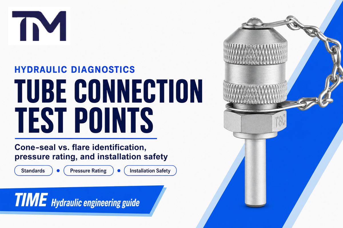
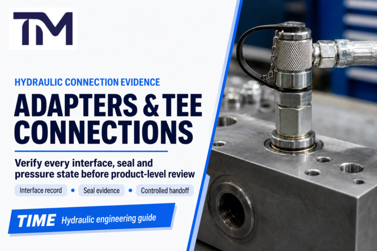
Tube connection test points are mechanical fittings that give a hydraulic system a definite location at which a pressure gauge, sensor, or sampling hose can be connected directly to the tube line itself, across various applications in mobile and industrial hydraulics. If a search for that specific phrase brought up pages featuring printed-circuit-board test points, that’s a naming collision, not a mistake – on hydraulics, a tube connection test point is a mechanical fitting, not an electrical connector port.
Quick Specs
| Connection families | 24-degree cone (DKO / cutting-ring, ISO 8434-1) and 37-degree flare (JIC, SAE J514 / ISO 8434-2) |
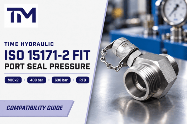
| Diagnostic-side interface | Separate from the tube-side connection — typically an M16x2 quick coupling per ISO 15171-2 |
| Built-in feature | Most bodies carry a self-sealing check valve and a dust protection cap, so the port stays sealed and clean when no gauge or hose is attached |
| Common materials | Carbon steel, 304 or 316L stainless steel body; NBR, FKM, or EPDM seal |
| Typical use | Pressure monitoring, diagnostics, and approved fluid sampling on a hydraulic tube line, often supplied as part of a gauge and hose kit |
Cone-Seal vs. Flare Fittings: The Two Tube-Connection Test Point Families
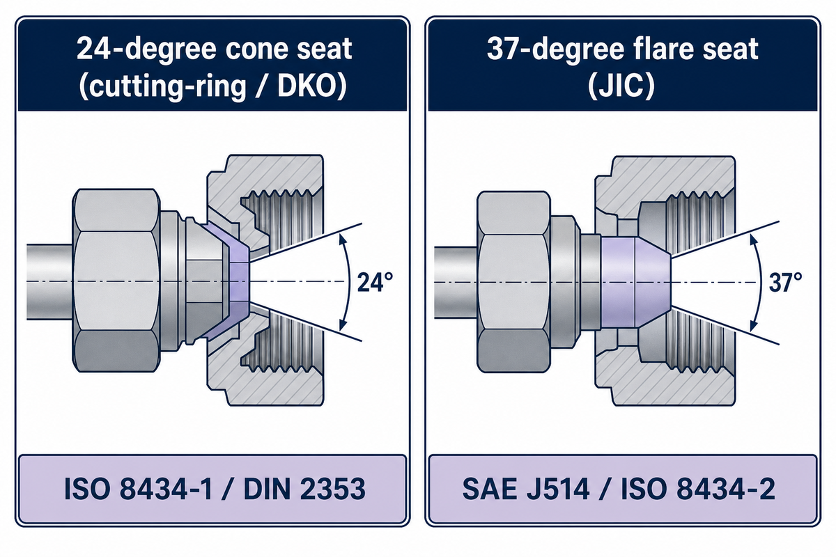
A tube connection test point belongs to one of two families of fittings – it’s the geometry of the seats, not their nominally stated size, that differentiates the families. Cone-seal fittings seal with a conical profile on a 24-degree angle, available with either a cutting-ring or O-ring seal. Flare fittings seal with a 37-degree, flared tube end pressed against a matching seat. Conflating the two is the most common order specification error made on tube connection test points.
The cone-seal family is standardized in ISO 8434-1, which covers 24-degree cone connectors using a cutting ring and an O-ring seal cone, the configuration commonly called DKO. A cutting-ring version of the same 24-degree family bites into the tube wall during assembly instead of relying on an O-ring alone; both share the same seat angle but seal differently, so a cutting-ring nut is not a drop-in swap for a DKO nut even though the cone angle matches. The flare family uses a 37-degree flared tube end, standardized in the JIC-style world as SAE J514 in North America and ISO 8434-2 internationally, two standards bodies describing the same geometry, not two competing designs.
💡 Pro Tip
A legacy European drawing may still label the 24-degree cutting-ring family under the older national standard DIN 2353. Treat a DIN 2353 callout on an older machine as the same 24-degree seat family as ISO 8434-1, but confirm the specific nut and ring generation before ordering a replacement, cutting-ring geometries were revised between editions.
Neither family is a diagnostic coupling on its own. The M16x2 quick-disconnect coupling used for live pressure readings, standardized separately under ISO 15171-2, is a distinct interface that sits downstream of the tube connection, a point covered in full later in this guide, since the two decisions (tube-side connection, then diagnostic-side coupling) are made independently. Manufacturers including Parker, STAUFF, and Tompkins all publish test point fittings across both families, which is useful context when a buyer wants to confirm that a specification is an industry norm rather than a single supplier’s convention; a buyer can draw on more than one qualified source with confidence, though the right family for a given order still depends on the specific application, fluid, and pressure rather than on brand preference alone.
Which Standard Governs Your Fitting: ISO 8434-1, ISO 8434-2, SAE J514, or Legacy DIN 2353
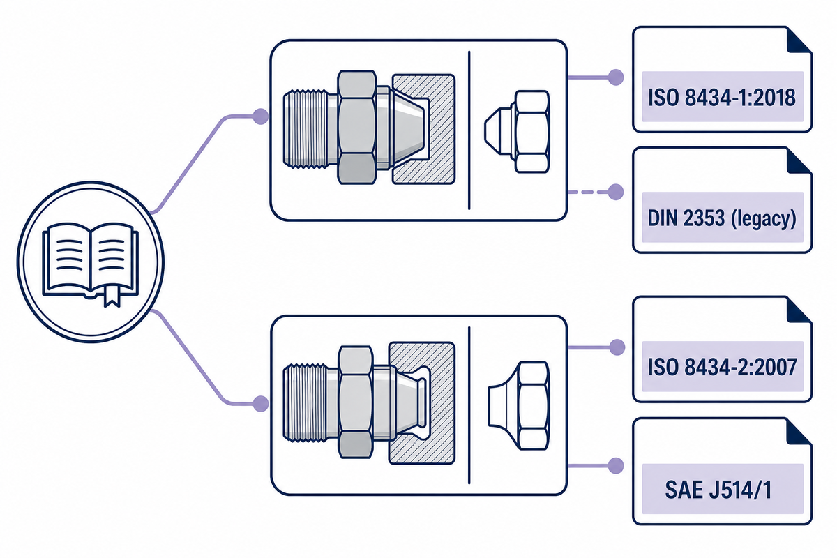
The standard number on a drawing tells you the connection family and its dimensional rules, not whether a specific supplier’s part is interchangeable with another’s. ISO 8434-1:2018 is the current, in-force edition covering 24-degree cone connectors with cutting ring and O-ring seal cone; a committee draft for a future revision exists on ISO’s own catalogue, but it has not replaced the 2018 edition and should not be treated as the governing document yet.
| Standard | Family | Seat angle | Legacy / equivalent name | Scope caveat |
|---|---|---|---|---|
| ISO 8434-1:2018 | Cone-seal (DKO) | 24 degrees | DIN 2353 (legacy) | Defines dimensions only; does not certify any single supplier’s part as conforming |
| ISO 8434-2:2007 | Flare (JIC-style) | 37 degrees | SAE J514 counterpart | Second edition, technically revised from the 1994 first edition |
| SAE J514/1 | Flare (JIC) | 37 degrees | ISO 8434-2 counterpart | General and dimensional specification for 37-degree flared tube fittings |
| DIN 2353 | Cone-seal, cutting-ring | 24 degrees | Superseded by ISO 8434-1 | Still marked on older machine drawings; confirm nut/ring generation before ordering |
| ISO 15171-2:2016 | Diagnostic coupling (M16x2) | Not applicable — quick coupling | None | A separate interface from the tube connection; do not infer tube-side thread from it |
| ISO 19879:2021 | Test methods (all families) | Not applicable | None | Specifies test methods for evaluating tube connections; does not set one universal pressure-ratio rule |
| ISO 1307 | Hose bore sizing (adjacent) | Not applicable | None | Governs hose inside-diameter tolerance, not tube-fitting pressure rating |
| EN ISO 4413 | System-level safety (all families) | Not applicable | None | Requires the whole assembled system, not just one fitting, to withstand maximum operating pressure |
| ISO 19598 | Finish/plating (adjacent) | Not applicable | None | Covers Cr(VI)-free zinc-alloy electroplated finish, not the connection geometry itself |
The tube-side seat covered in this table is a separate question from the port thread on the machine side, which follows its own family of standards, NPT, BSP, or metric O-ring boss are common examples, covered in full in our dedicated thread guide rather than repeated here. A standard swap does not silently change what you are buying, provided the two standards genuinely describe the same geometry, SAE J514 and ISO 8434-2 do, for the 37-degree flare family, confirmed independently by three separate fitting manufacturers’ technical pages in addition to ISO’s own catalogue entry. What a shared standard number cannot do is prove that two different suppliers’ parts are interchangeable down to seal compound, surface finish, and pressure rating; the standard fixes geometry, not a specific supplier’s conformity.
How to Identify Your Connection Type Before You Order
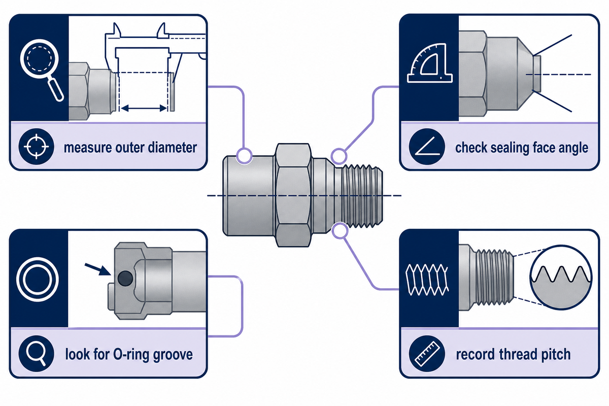
Identify a tube-connection test point by seat geometry and measured dimensions, not by the part’s general appearance. Thread designation alone doesn’t define the seat angle, sealing face, O-ring arrangement, or mating geometry, as SAE J514’s own dimensional specification makes clear — two fittings can share a thread size and still be incompatible if the seat form differ.
- Measure the tube outside diameter and note the light or heavy series before treating the nut thread as an identifier.
- Check the sealing face shape with calipers or a seat gauge: a 24-degree cone looks noticeably shallower than a 37-degree flare when compared side by side.
- Look for an O-ring groove on the cone face, its presence points to a DKO O-ring seal cone rather than a plain cutting-ring assembly.
- Record thread pitch and measured major diameter together; matching pitch alone has passed off mismatched families before.
- Photograph the installed connection and any visible part marking before disassembly, a marking that has worn illegible is common on older machines and the photo become the fallback identification record.
- Keep the port capped whenever a gauge or hose isn’t attached, to help prevent contamination from entering the system while you complete identification.
Quality control at this stage is mostly about discipline, not equipment: taking the time to measure and photograph before ordering helps ensure an efficient, correct-on-the-first-attempt replacement rather than starting a second clarification round.
How Do You Identify a Tube Fitting’s Seat Geometry Without a Drawing?
Compare the sealing face shape and thread pitch together against a known reference, since neither measurement alone reliably identifies the family — a caliper check on both dimensions at once is what actually narrows down the correct connection.
On an installation with no available drawing, hydraulic-thread identification requires more than nominal diameter: taper or parallel thread form, pitch, measured major diameter, and the sealing face must all be checked together before a connection can be matched. A caliper reading of thread pitch narrows the field, but the cone or flare angle at the sealing face is what finally distinguishes a 24-degree cutting-ring or DKO connection from a 37-degree JIC flare, since manufacturers across the industry use different thread families on machines that otherwise look similar. Where the marking is worn away entirely, sending measured dimensions and a clear photograph for supplier review is faster and more reliable than guessing from a parts catalogue photo.
Pressure Rating: Why the Weakest Component Sets Your Ceiling
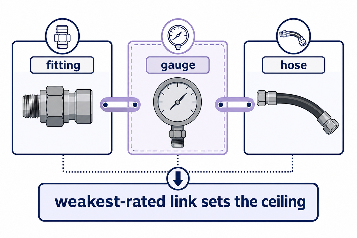
The safe working pressure of an assembled tube-connection test point is set by its lowest-rated component, not by the highest number printed on any single part in the chain. EN ISO 4413 requires every part of a hydraulic system to be protected against pressure exceeding the system’s maximum working pressure or that part’s own rated pressure, preferably through one or more pressure relief valves sized for the circuit.
📐 The Weakest-Rated-Component Rule
A 2018 MSHA fatality investigation found that a coal-processing facility’s maintenance crew reconfigured a service truck’s hydraulic system without depressurizing it first, unintentionally routing 3,000 psi into a circuit built around an 800 psi-rated brass fitting. The fitting burst, and the temperature sensor it held became a projectile that fatally injured the mechanic examining the system. MSHA’s root-cause finding was inadequate task training on the hydraulic system, not the fitting’s rating alone, but the fitting’s own 800 psi limit is exactly what the reconfigured circuit exceeded, nearly four times over. Depressurize and lock out a hydraulic circuit before modifying it, and specify every fitting, gauge, and hose in a diagnostic chain against the system’s actual maximum pressure, not the pressure the point is normally expected to see.
Suppliers commonly quote a burst-to-working-pressure ratio near four to one as a safety-factor convention, and test protocols such as ISO 19879 specify the methods used to evaluate tube connections, stud ends, and flange connections under pressure. That said, ISO 8434-1 itself states that numerous factors affect satisfactory performance and that its working-pressure figures are not guaranteed minimums, a supplier’s quoted ratio is a useful planning convention, not a substitute for the specific pressure rating documented on that model’s own drawing.
The whole point of the connection is to monitor hydraulic pressure safely at a fixed point, and the diagnostic-coupling side of that same chain is commonly rated up to 630 bar under ISO 15171-2, a separate figure from the tube connection’s own working pressure, not one to assume automatically applies to it. An unplanned fitting failure costs far more in downtime and cleanup than the price difference between a correctly rated part and an undersized one, which is the practical reason to measure pressure requirements before ordering rather than after a failure.
Material and Finish Options for Tube-Connection Test Points
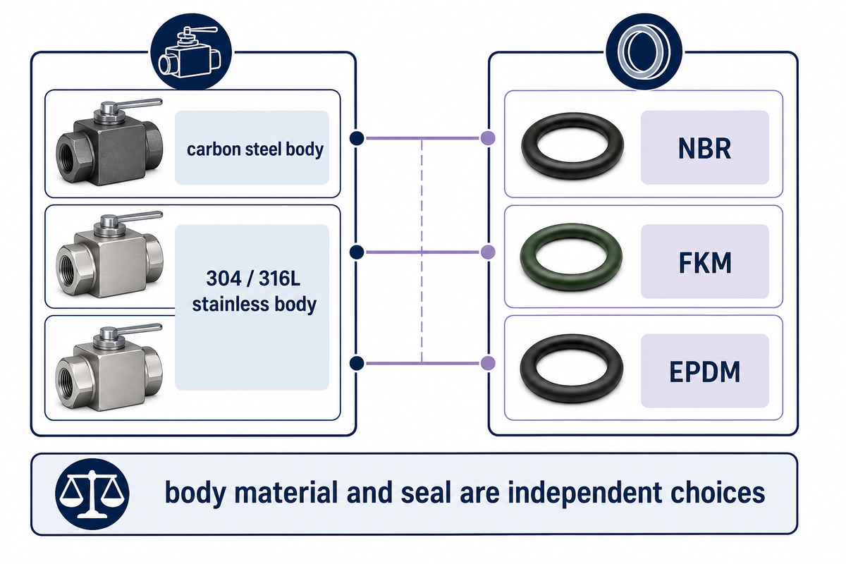
| Option | When it applies |
|---|---|
| Carbon steel body | General indoor hydraulic circuits without corrosive fluid or washdown exposure |
| 304 stainless steel | Moderate corrosion exposure, food-adjacent or outdoor equipment |
| 316L stainless steel | Chloride or reducing-acid exposure — the added molybdenum content gives 316L better resistance than 304 in these conditions, though the right choice still depends on the specific fluid and concentration |
| Zinc / Cr(VI)-free zinc-nickel finish | Carbon-steel bodies needing a corrosion-resistant plated surface without hexavalent chromium, per ISO 19598 |
| NBR / FKM / EPDM seal | Selected by fluid compatibility and operating temperature range, not by body material alone |
Body, Finish, and Seal-Compound Type Reference
| Material type | Common grade | Fluid / temperature fit | Typical note |
|---|---|---|---|
| Carbon steel body | Standard grade | General indoor circuits, non-corrosive fluid | Lowest cost; needs a compatible finish in humid environments |
| 304 stainless steel body | Austenitic grade | Moderate corrosion exposure, food-adjacent or outdoor use | Broadly available, good weldability |
| 316L stainless steel body | Austenitic low-carbon grade | Chloride or reducing-acid exposure | Added molybdenum improves pitting resistance over 304 |
| Zinc / Cr(VI)-free zinc-nickel finish | Plated finish type | Carbon-steel bodies needing corrosion protection | Meets ISO 19598; no hexavalent chromium |
| NBR (nitrile) seal | Elastomer type | Mineral oil, moderate temperature | Common default; not for phosphate-ester fluid |
| FKM (fluoroelastomer) seal | Elastomer type | High-temperature service | Broader chemical resistance than NBR, higher cost |
| EPDM seal | Elastomer type | Phosphate-ester or water-glycol fluid | Not compatible with petroleum-based mineral oil |
| PTFE seal / back-up ring | Polymer type | Extreme chemical inertness, wide temperature range | Used as a back-up ring behind an elastomer O-ring more often than as the primary seal |
| Light / heavy thread series | Dimensional series type | Matched to tube outer diameter | Sets nut and ferrule size, independent of body material choice |
High-value body material will only contribute towards increased durability and robustness if correctly partnered against the fluid being presented to it – there are several combinations of seal materials and body designs that will pair well with specific applications, be these oil or more corrosive, process fluids, and selecting incorrectly will nullify the value even of a high-value component. Improvements to body materials are no replacement for a documented pressure or seal rating – connection geometry must still be assessed against the relevant standard family (see ISO 8434-1 and ISO 8434-2 above) on its own merit and not that of the bodies upon which they’re mounted. Where a supplier suggest their body material and/or finishing is appropriate in the absence of certification evidence, consider this to be solely a ‘first party’, as-yet unverified assertion rather than an established fact, a point this guide addresses directly later on.
Installing a Tube-Connection Test Point Without Creating a Leak Path
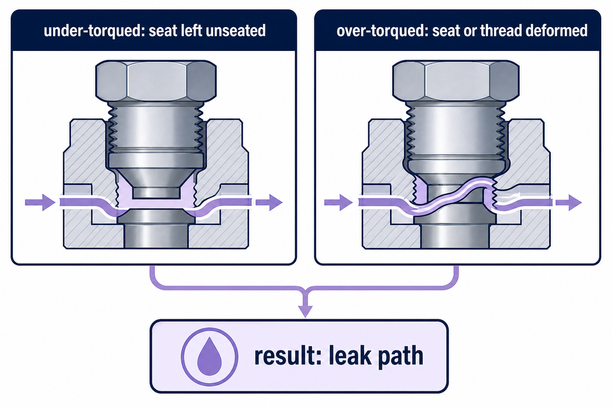
Most tube-connection leaks trace back to installation, not to a defective part. Both over-tightening and under-tightening are documented, comparably common causes: an under-torqued nut leave the seat unseated, while an over-torqued nut deforms the seat or thread and creates the exact leak path it was meant to prevent. Routine maintenance and troubleshooting both start the same way, confirm which family and size is installed before assuming the leak come from the seal rather than the assembly itself, which lets a technician work through a suspected leak efficiently instead of swapping parts by trial and error.
✔ Do
- Torque to the manufacturer’s specified value, then check for leaks under normal operating pressure before returning the machine to service.
- Confirm the tube material is soft enough to flare cleanly before attempting a field flare, a flare fitting require a prepared tube end, while a cutting-ring or DKO connection doesn’t.
- Inspect the sealing face and O-ring for scratches or nicks before every reassembly, not only on first installation.
- Replace a worn-out, degraded, or gouged seat with a new one, rather than attempting a field repair – it is more efficient in the long run than reworking a marginal seal that fail again later.
⚠ Don’t
- Don’t torque past spec in the attempt to “make sure it seals” – NASA’s own bolted-joint tests have shown that torque and clamping force aren’t necessarily related in the real world since friction at the thread and bearing face will absorb a large, unpredictable portion of the torque you apply.
- Don’t reuse a gouged or previously over-torqued seat without checking it first.
- Don’t assume a matching thread confirm a matching seat family.
Safety Boundaries Before You Pressurize a Test Connection
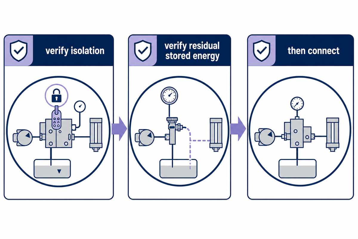
A tube-connection test point is an intended contact point with high-pressure fluid, and that changes what preparations are needed before you connect anything to it. Government guidance on equipment and pressure-test procedures requires controlling the hazards of stored energy and the risk of possible hose or connector ejection before a connection is made, not after a leak appears.
“Hydraulic and pneumatic energy sources… could cause injury to employees if unexpectedly released during servicing.”
On mobile and stationary hydraulic machinery alike, an OSHA incident record is made of high-pressure hydraulic fluid piercing a worker’s skin after a loose hose coupling and an internal O-ring failure during testing. HSE guidance is explicit that its generally quoted 7 bar injection-injury figure is based on anecdote, not a safe threshold – serious documented injection injuries have occurred above 100 bar, and without prompt medical attention a patient can suffer severe throbbing pain within 4 to 6 hours that’s resistant to standard painkillers, with delayed attention increasing the chance of amputation.
⚠️ Important
If a fitting is being replaced and not newly installed, HSE guidance considers verification of the replacement to be an individual pressure test, and expects the replacement to match the original equipment specification – not a visually close substitute. Verify isolation, residual stored energy, and part compatibility before treating any connection as safe to pressurize.
What Personal Protective Equipment Is Necessary Before Pressurizing a Test Connection?
Eye protection, cut-resistant gloves rated for the fluid in use, and a face shield for high-pressure work are standard equipment, alongside a documented energy-control procedure that confirms isolation before anyone connects a gauge.
Beyond personal protective equipment, the underlying control is procedural: a hydraulic test point’s connection capability does not replace the applicable employer hazardous-energy control program or a machine-specific service procedure. Personal protective equipment reduces the consequence of an unexpected release; it does not substitute for confirming isolation state, verifying the fitting and hose are rated above the system’s maximum pressure, and following the manufacturer’s stated test or servicing sequence before the connection is made.
Tube Connection vs. Hose Connection vs. Diagnostic Quick-Coupling: Choosing the Right Interface
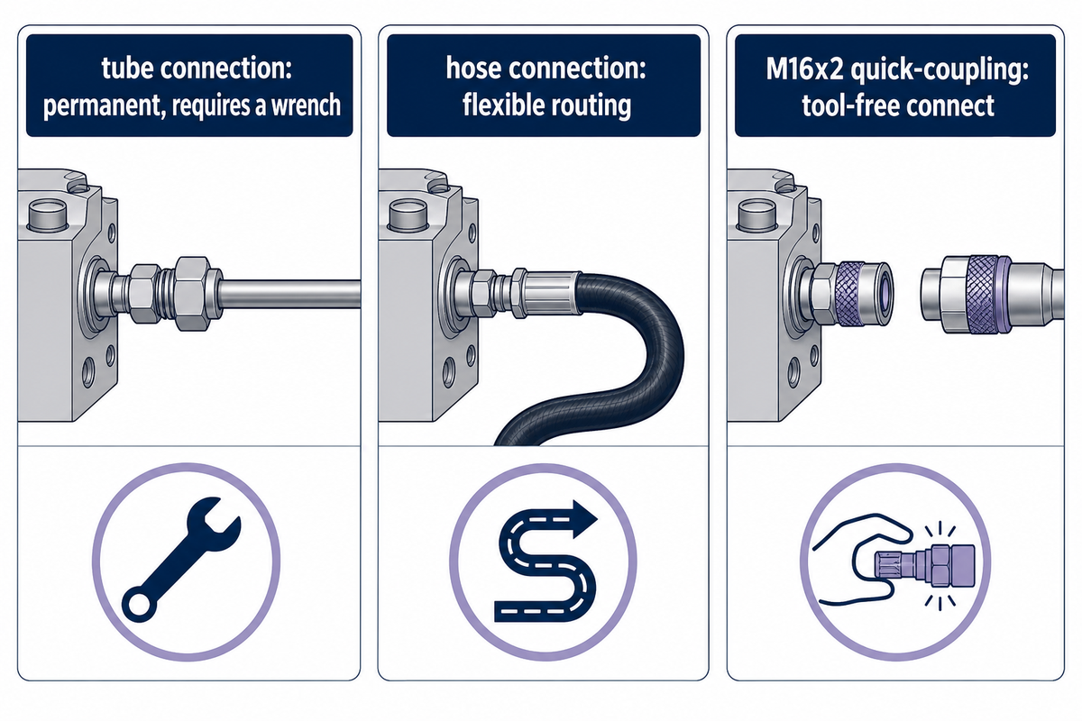
A tube-connection test point, a hose-connection type, and an M16x2 diagnostic quick-coupling solve different parts of the same problem, and choosing among them is a separate decision from choosing the cone-seal or flare family.
| Interface | Typical use case | Tool-free connect |
|---|---|---|
| Tube connection (cone-seal or flare) | Permanent installation into a tube line or machine port | No — requires a wrench |
| Hose connection | Flexible routing between components, service loops | No — crimped or field-attachable fitting |
| M16x2 diagnostic quick-coupling (ISO 15171-2) | Repeated field diagnostic access without disturbing the permanent connection | Yes — connects under pressure without tools, within the coupling’s rated limit |
The tube connection joins the test point body to the hydraulic line; the diagnostic coupling, sometimes sold as a gauge adapter or paired with a dedicated test point hose, joins that body to whatever gauge, sensor, or hose takes the reading. Some catalogues still call these diagnostic couplings “test couplings,” and pressure testing equipment built around them is a different purchase from the tube-side fitting or adapter that anchors the whole assembly to the machine. For the coupling side specifically, compatibility limits, connect-under-pressure permission, and cross-brand interchange, see this site’s ISO 15171-2 compatibility guide. For matching a port thread on the machine side, see the hydraulic test thread guide.
Why Bore Size Changes Your Flow Budget More Than You’d Expect
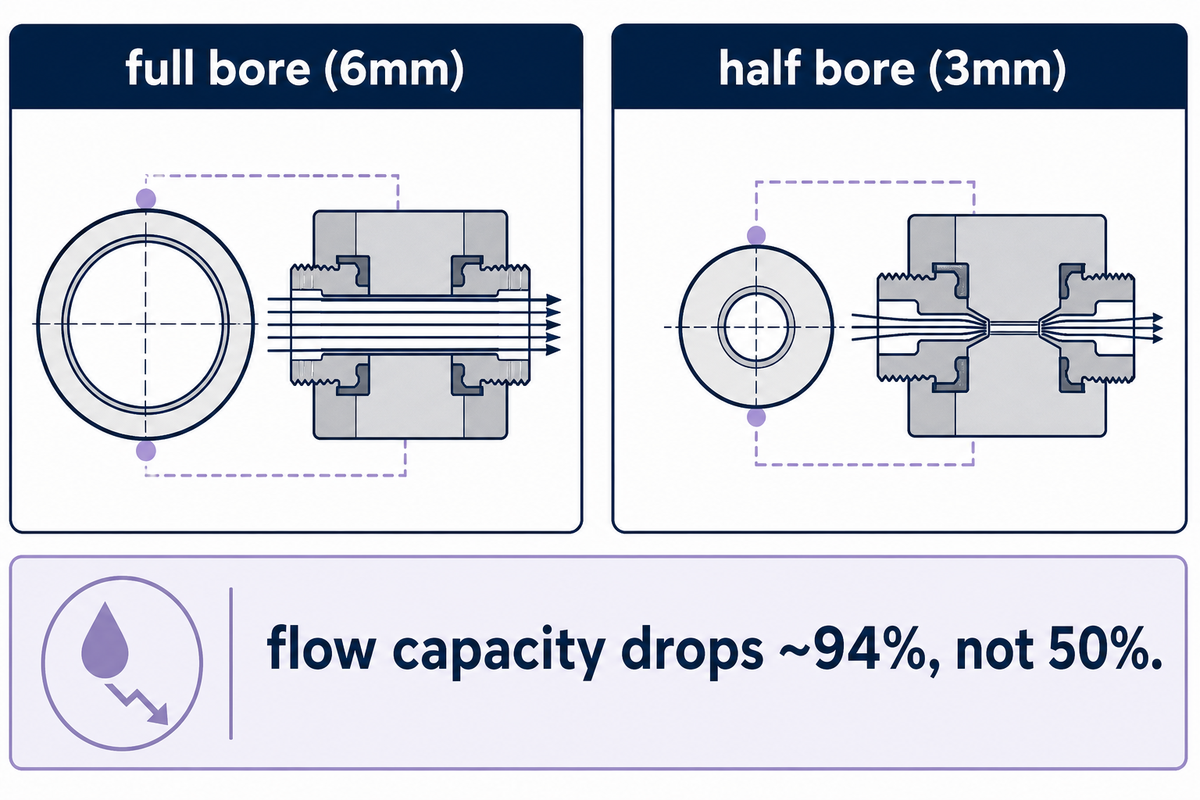
Laminar flow through a straight tube scales with the fourth power of the tube’s radius, so halving the radius of an idealized straight bore reduces its theoretical flow capacity to roughly one-sixteenth, not one-half. That relationship, Poiseuille’s law, explains why bore size deserves more attention than it usually gets on a test connection also used for sampling or bleed-down, not just a static pressure reading — a caveat NIST’s own review makes explicit.
For example, shrinking an idealized bore from 6mm to 3mm cuts theoretical flow capacity by about 94%, not the 50% a linear guess would suggest.
📐 Engineering Note
Poiseuille’s law describes laminar flow through a long, straight, smooth-walled tube. A tube-connection test point is a short, geometrically complex passage, NIST’s own review of pipe-fitting pressure-loss data concludes that most existing loss data aren’t representative of modern fittings and flow conditions, because entrance effects, direction changes, and cross-section changes in a compact fitting aren’t captured by the idealized straight-tube formula. Treat the fourth-power relationship as the reason bore size matters this much, not as a precise flow-rate prediction for your specific fitting geometry.
Verifying a Supplier’s Certification and Customer Claims Before You Buy
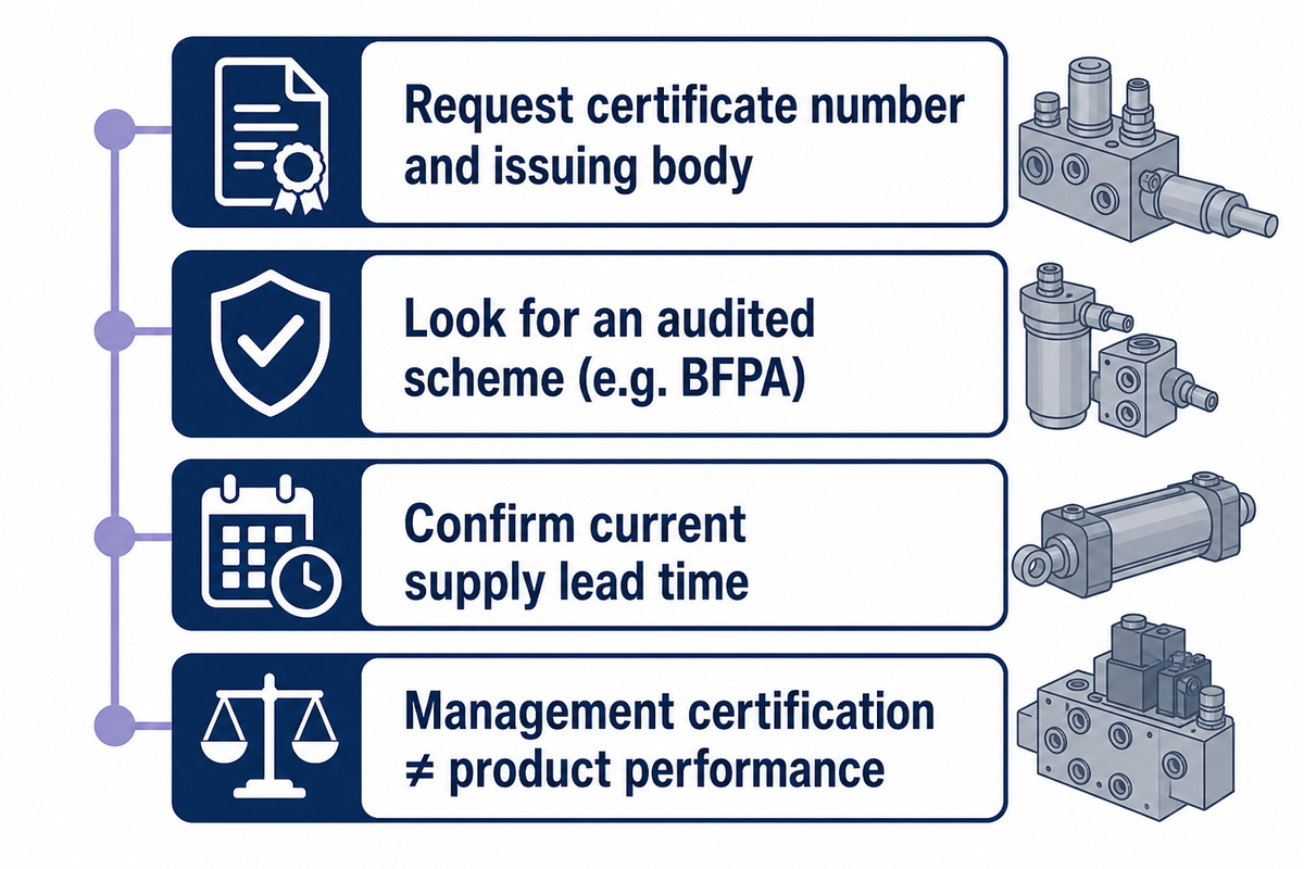
Simply stating “ISO certified” does not necessarily indicate adherence to the corresponding specification for the specific test point you’re looking for. ISO states quite clearly it does not perform certification or issue certificates, rather, it establishes specifications, and a separate third party inspects a company (to verify compliance to an ISO standard) for that system of operations; and a successful inspection only results in certification, for management standards not product performance.
- Be inquisitive – ask for the Certificate number, the name of the Body that granted said Certification, and the scope of that Certification. Certifications related to quality management for the system procedures don’t guarantee a specific part’s dimensional precision or its stated pressure service rating.
- Ask whether a customer-referenced model is a current service listing, authorized to be supplied presently, and whether the dealer would be amenable to show a supply requisition form (invoice for purchase history).
- Opt for an audited and certificated system, such as the BFPA Approved Hose Assemblies Scheme; member assemblies of which are audited, and these audit findings mean that the accreditation itself has weight, far more than a ‘self-certified’ claim.
- Maintain a shorter preferred-supplier inventory instead of investigating qualification on every project, and check out current available supply lead times for that particular fitting configuration, rather than relying on the price of a previous configuration.
The same standard applies to this guide’s own sourcing: TIME Hydraulic’s stated ISO and SGS certifications, 5,000-square-metre production facility, and named-customer relationships are the supplier’s own claims, presented here as first-party statements pending independent documentary verification, not as independently confirmed facts.
When a Tube-Connection Interface Is the Wrong Choice
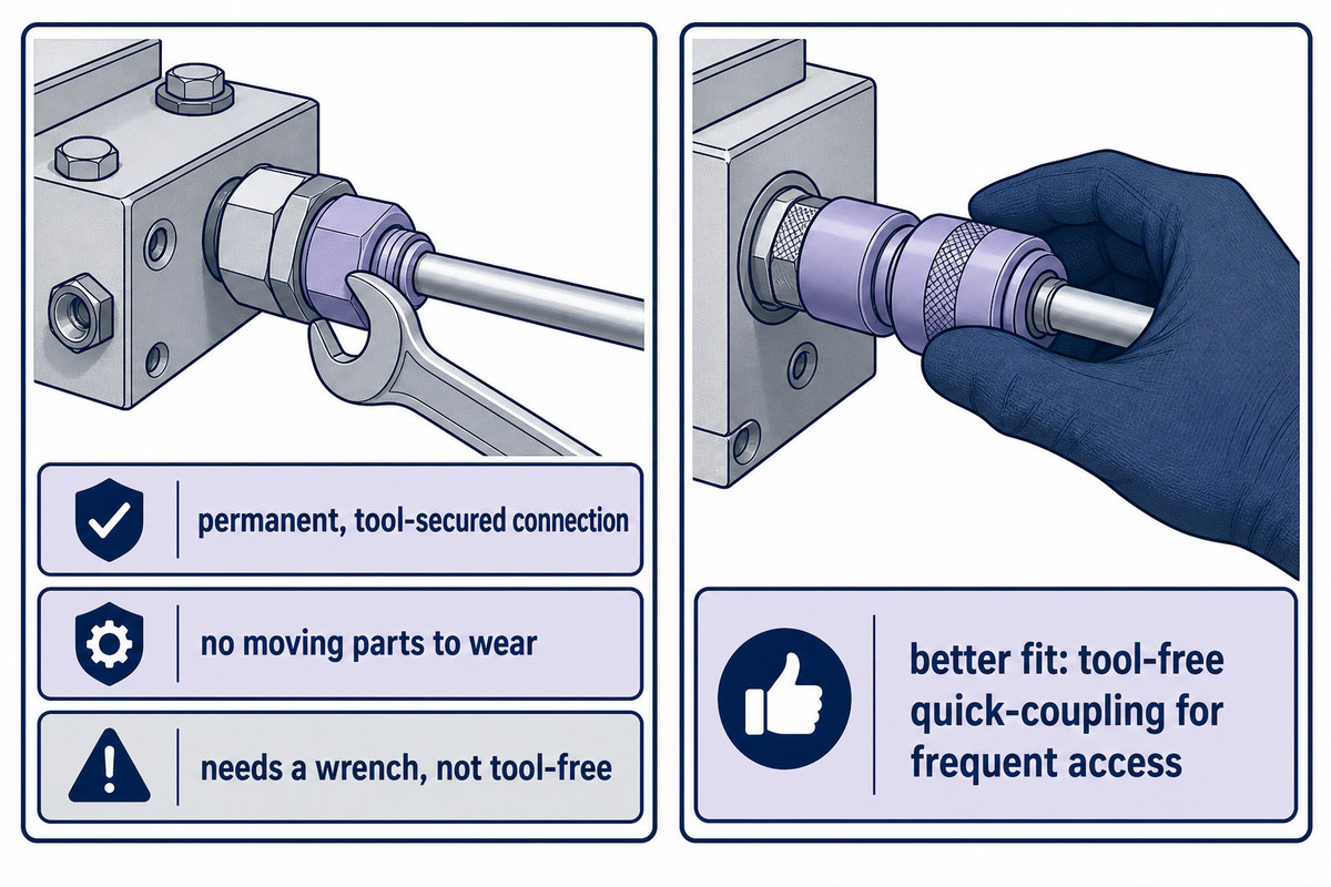
✔ Advantages
- Permanent, tool-secured connection suited to a fixed pressure-monitoring point
- No moving parts to get fatigued and work hardened; unlike a continually cycled quick-coupling
- Wide standards coverage (ISO 8434-1, ISO 8434-2, SAE J514) makes cross-referencing a replacement part straightforward
⚠ Limitations
- Requires a wrench and, for flare types, a tube soft enough to flare. So if you need frequent on/off access in the field with quick connections, it might not be your best choice.
- Generally not suitable when a fluid/air/signal access point needs very quick, repeated tool-less connection for diagnostic applications – use one of those readily available M16x2 (or similar size) quick-coupling arrangements for such use.
- Standardized geometry doesn’t guarantee cross-brand interchangeability without checking seal compound and finish
Choose a diagnostic quick-coupling instead of a tube connection when a technician needs to connect and disconnect a gauge repeatedly without tools, and choose a hose connection instead when the routing need to flex rather than stay fixed. Tube-connection test points earn their place when the connection is meant to stay put.
Frequently Asked Questions
Q: What’s the difference between a cone-seal and a flare tube-connection test point?
A cone-seal fitting seals on a 24-degree cone under ISO 8434-1, while a flare fitting seals on a 37-degree flared tube end under SAE J514 or ISO 8434-2.
Even where thread size looks compatible, the seat angle that actually forms the seal is usually different between the two styles, and it must always match on both sides of any connection you make. A shared thread size does not make a cone-seal and a flare fitting interchangeable, the sealing geometry, not the thread, is what has to match. Always check the seat angle directly rather than assuming it from thread size or general appearance.
Q: Can I mix ISO 8434-1 and SAE J514 fittings on the same hydraulic system?
Yes, because they cover different, non-competing connection families that a hydraulic system can use side by side, but do not mix the two families within a single connection point or expect the seats to seal against each other.
ISO 8434-1 (24-degree cone) and SAE J514 (37-degree flare) are separate standards for separate seat geometries, and a system commonly uses both families in different locations. What you cannot do is join a 24-degree cone fitting to a 37-degree flare fitting and expect a seal, match seat angle to seat angle at every individual connection.
Q: What personal protective equipment is necessary when working with pressurized test connections?
Eye protection and gloves rated for the hydraulic fluid in use are standard minimums, backed by a documented energy-control procedure that confirms isolation and residual pressure before any connection is made.
Your PPE has a critical role to play in reducing injury in the event that something does fail, that’s why equipment matters so much; but PPE is an addition, not a substitute to taking the right steps of equipment first confirming isolation and then verifying there’s no stored energy in the system (and not forgetting to isolate any back feeds into the circuit). (Consultation of the safety section of this document outlines the correct safety procedures for working with hydraulic systems).
Q: How should a tube-connection test point be inspected before use?
Check the sealing face and O-ring for scratches, confirm the marking or measured dimensions match the intended part, and verify no prior over-torque damage before putting the connection back into service.
If a seat face or thread has previously been severely marred from repeated over-tightening, that damage will prevent a good seal even if the fitting was otherwise correctly chosen for the connection.
Q: Why is a check valve important in a tube-connection test point assembly?
The built-in check valve keeps the port sealed against system pressure whenever no gauge or hose is attached, so the connection stays leak-free between uses.
Without that valve, an open test point would leak continuously whenever it was not in active use, which is why most bodies on the market include one as standard rather than optional equipment. A worn or damaged check valve is one of the less obvious causes of a slow weep at a port that otherwise looks undamaged, and it is easy to overlook during a visual inspection focused only on the external seat and threads. Confirm the valve seats fully closed as part of the same inspection you already run on the seal face and threads, particularly on a test point that sees frequent gauge connection and disconnection cycles, since repeated cycling is exactly the condition that wears a check-valve seat over time.
Q: What’s the risk of neglecting maintenance on a tube-connection test point?
Documented field data puts hydraulic fitting leak rates as high as 1 to 13 percent even under normal service, and a neglected seat only raises that risk.
Published in 2012 and still widely cited, an ASME review of mobile-equipment hydraulic leaks found in-plant leak rates between 1% and 25%, and field leak rates between 1% and 13%, driven by installation quality, vibration, and assembly complexity rather than any single cause, figures still referenced in current industry discussion despite the underlying study’s age. Waiting for a visible weep before inspecting a test point already misses the earlier point where a scratched seat or a slightly loose nut could have been caught.
Why We Write This
TIME Hydraulic manufactures hydraulic test points and hoses across multiple thread and seal families under the IKIN product name, and states that it specializes in diagnostic connections rather than a broad hydraulic-component catalogue. This guide draws on the same cone-seal and flare standards documented on our own tube-connection test point page, plus published ISO, SAE, OSHA, HSE, MSHA, and NIST sources, to answer the identification, installation, and safety questions a buyer or technician asks before ordering a replacement part.
Related Articles
- ISO 15171-2 Compatibility Guide for M16x2 Hydraulic Test Points: diagnostic-coupling compatibility, connect-under-pressure limits
- Hydraulic Test Connection Thread Guide: matching port thread, seal, and test hose
- Hydraulic Test Hoses & Fittings Guide: hose assembly evidence and supplier verification
- Hydraulic Test Point Selection Guide: broader selection factors beyond connection type
- A Measurement-First Guide to Hydraulic Test Points and Couplings: measurement-integrity and diagnostic-access process
References & Sources
- ISO 8434-1:2018 scope: International Organization for Standardization
- ISO 8434-2:2007 scope: International Organization for Standardization
- EN ISO 19879:2021 test methods for metallic tube connections
- ISO/CD 8434-1 committee draft status: International Organization for Standardization
- OSHA, Control of Hazardous Energy overview
- HSE, hydraulic fluid injection injury guidance
- MSHA, Fatality #12, November 29, 2018, Final Report
- ISO 4413:2010, Hydraulic fluid power general rules and safety requirements
- NASA Spinoff, bolt clamp-force and torque measurement
- NIST, State-of-the-art review of pressure losses in pipe fittings
- ASME, Failure Mode Analysis of Mobile Equipment Hydraulic Leaks
- Practical Machinist, practitioner discussion on JIC and SAE O-ring boss fitting reliability
- DIN 2353:2013-01, Non-soldering compression fittings with cutting ring — complete fittings and survey
- ISO 1307:2006, Rubber and plastics hoses — hose sizes, bore diameters, and length tolerances
- EN ISO 19598:2016, Metallic coatings — electroplated zinc and zinc-alloy coatings with Cr(VI)-free supplementary treatment