
Get in touch with TIME Company

From test point to pressure gauge
Hydraulic Test Hoses & Fittings
TIME supplies hydraulic test hose product routes for pressure test work, condition monitoring and service diagnostics. Select the hose bore, both end connections, fluid, working pressure, connection state and finished length before our team releases a drawing.
Selection summary
Hydraulic Test Hose Selection at a Glance
A hydraulic pressure test hose is a measurement link, not an isolated catalogue item. A hydraulic test point hose still needs its bore, reinforcement, cover, end fitting, adapter and pressure gauge connection reviewed as one chain.
Start with the lowest confirmed rating: under SAE J517, the complete hydraulic pressure test chain cannot be assigned a working pressure above its lowest-rated applicable component.[2] A converted psi value or a family label is not configuration evidence.
01 Product range
DN2, DN3 and DN4 hydraulic hose routes plus custom mixed-end assemblies
02 Quotation planning
A reviewed response within four business days
03 Prototype planning
10 to 30 business days for custom hose prototypes after drawing approval
04 DN4 planning
Four to six weeks after specification confirmation
05 Quality release
Every hydraulic test hose assembly is inspected individually before shipment
06 Seal approach
Cone-seal design, subject to the ordered connection drawing
07 Product focus
We focus exclusively on hydraulic test points and test hoses
08 Company and brand
TIME Hydraulic is the operating company, and IKIN is our product trademark
Hydraulic Test Hose Product Navigator
Hydraulic Test Hose Product Families
Use these four routes to reach the right level of product detail without forcing a DN or end style from a single measurement. TIME manufactures hose assemblies and end components, while the current drawing determines what can be combined.
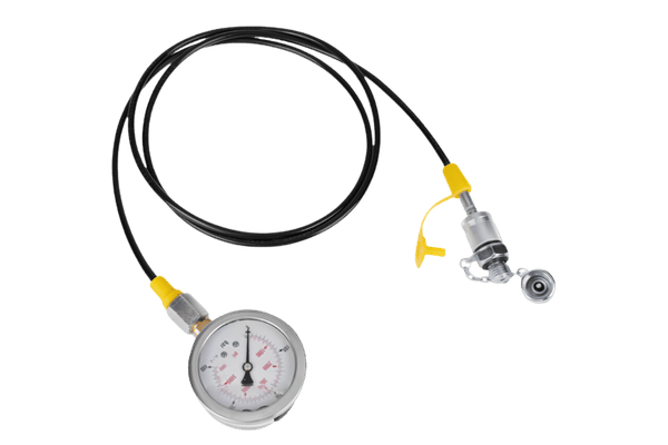
Compact-bore route
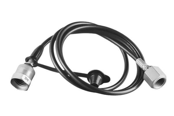
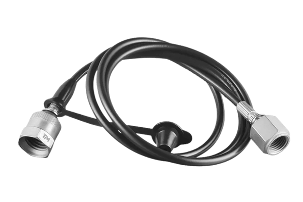
DN2 & DN3 Microbore Test Hoses
Review the 2 mm DN2 family and the build-to-application 3 mm DN3 route when compact pressure measurement lines are required.
- DN2 and DN3 bore discussion
- Microbore hose construction inputs
- Current connection and drawing review
Larger-bore route
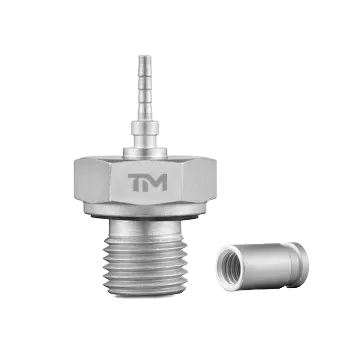
DN4 Hydraulic Test Hoses
Open the DN4 route when the 4 mm family, its construction and part-number pressure evidence need to be reviewed.
- 4 mm nominal bore family
- Model-specific working pressure record
- Construction and lead-time scope
Interface route
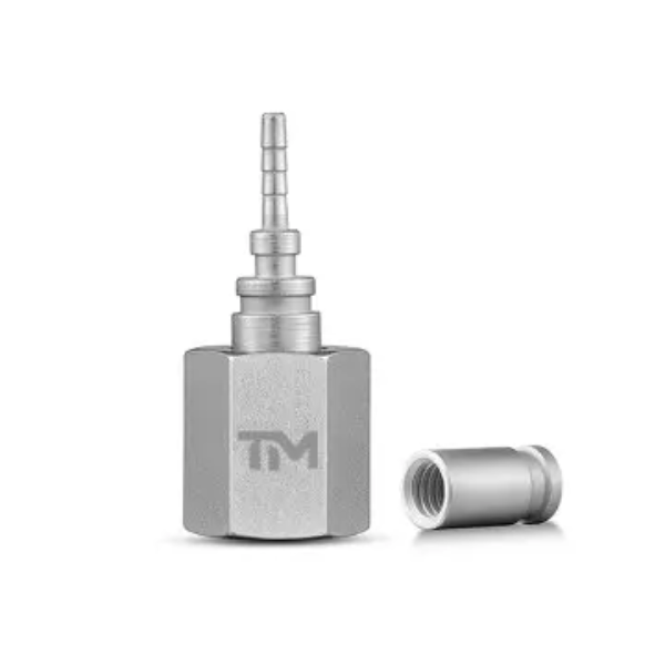
Hydraulic Test Hose End Fittings
Use this route when the machine-side or instrument-side connection geometry is the main unresolved point.
- Thread, pitch and sealing form
- Gauge, sensor and recorder ends
- Material and surface-treatment review
Drawing-led route
Custom Test Hose Assemblies
Choose a custom assembly when finished length, mixed ends, marking or order documents must be bound to one drawing.
- End A and end B definition
- Cut-to-length assembly input
- Marking and documentation request
Compatibility inputs
Hose, Fitting and Seal Material Options
Material names do not prove compatibility on their own. ISO 6605 treats the hose and attached fittings as an assembly test scope, so TIME reviews the hydraulic fluid, temperature range, external exposure, bend route and connection geometry before confirming any material set.
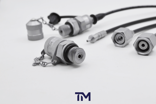
Thermoplastic or nylon core classes can be discussed for microbore test hose applications. The current part drawing must identify the actual core.
Synthetic-fibre reinforcement and protective cover options depend on bore, pressure class, routing and environment. Do not substitute appearance for the assembly record.
Carbon steel and corrosion-resistant finish paths are reviewed against the ordered fitting geometry. Surface protection must be named on the drawing.
304 and 316L stainless steel are option classes for suitable parts, not a promise that every end style is available in both grades.
NBR, FKM and EPDM are seal classes that require a fluid and temperature review. The seal in the ordered assembly must match the connection design.
Provide the exact fluid designation, minimum and maximum temperature, washdown chemicals and external corrosion conditions. The reviewed option is then bound to the drawing.
Both ends matter
End Connections and Surface Protection
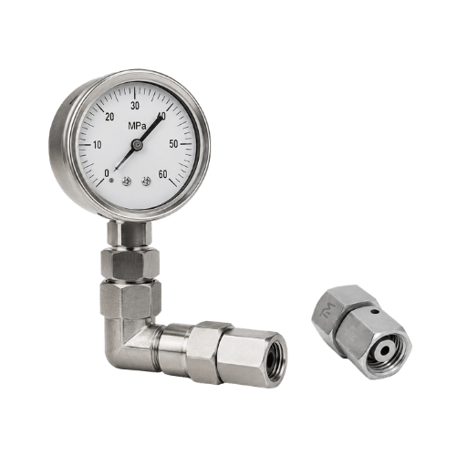
A test pressure hose must connect the installed test point to the selected gauge, sensor or data recorder without an assumed adapter. ISO 15171-2 defines a qualifying scope for M16 × 2 diagnostic couplings rather than a blanket fit claim, so TIME prepares a connection drawing after both interfaces and their sealing forms are identified.
Checkpoint
End-identification checkpoint: write each interface as thread, pitch, seat and seal, then define where finished length is measured. Hose marking and nominal bore do not settle either end. A close visual match remains an unverified connection until the drawing is checked.
Test coupling end
Record the interface designation, mating geometry and whether connection is planned in a depressurized or pressurized state.
Stud end
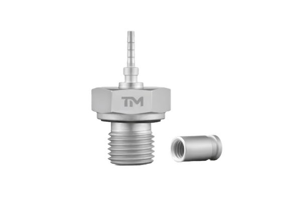
Provide thread, pitch, sealing form, installation depth and surrounding clearance from the current machine drawing.
Banjo route
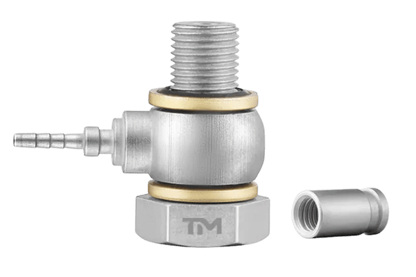
State bolt, port, sealing washer, orientation and envelope requirements before a compact angled route is reviewed.
24-degree cone route
Identify tube size, series, thread and cone geometry. A generic metric description is not enough.
O-ring-seal route
Define the face, groove and elastomer material together. Thread compatibility alone does not establish sealing compatibility.
Pressure-gauge connection
Supply the gauge thread, seal, full-scale range and calibration status along with the required hose reach.
Six-Input RFQ Brief
Organize both ends, fluid, pressure, connection state and finished length.
Complete-Chain Rating Checker
Compare user-entered ratings and identify the lowest stated component value.
Pressure Unit Converter
Convert MPa, bar, psi and kPa without treating conversion as product approval.
Terminology
Buyer terminology: a hydraulic test hose adapter, hydraulic test fittings and a hydraulic test coupling can describe different points in the connection chain. The drawing separates those parts before quotation.
Drawing-controlled scope
Pressure, Size and Connection Scope
The mismatch risk starts when one higher-rated component is treated as proof for the entire hose assembly. Because the lowest applicable rating controls, TIME Hydraulic engineers the review around the current drawing, the 2 mm, 3 mm or 4 mm bore route and the relevant standard evidence. The table therefore separates product identifiers, public-standard boundaries and commercial planning figures.
| Decision field | Published input | Release boundary |
|---|---|---|
| DN2 nominal bore | 2 mm / 0.079 in | Confirm model, reinforcement, ends and current working-pressure evidence |
| DN3 nominal bore | 3 mm / 0.118 in | Build-to-application route; drawing review required |
| DN4 nominal bore | 4 mm / 0.157 in | Confirm part number and configuration rating |
| Diagnostic interface input | M16 × 2 | Thread alone does not identify the complete coupling or seal |
| ISO 15171-2 connection scope | Connection under pressure up to 40 MPa for qualifying designs | Public-standard boundary; current product and machine evidence still govern |
| Custom prototype planning | 10 to 30 business days | After drawing approval and subject to the quotation |
| DN4 production planning | 4 to 6 weeks | After specification confirmation |
| End-fitting trial planning | From 100 pieces | Selected fitting family and quotation control |
Quotation planning
Product-Family Ordering Terms
Price depends on bore, end combination, material, finished length, marking, inspection documents and quantity. The written quotation states the final scope instead of publishing a price that omits those variables.
| Commercial field | Planning position | What to confirm |
|---|---|---|
| Reviewed quotation | Within four business days | Complete inputs, drawing status and requested quantity |
| Custom hose prototype | 10 to 30 business days | Drawing approval, material and end combination |
| DN4 production | Four to six weeks | Specification confirmation and order schedule |
| Selected hose assemblies | No fixed minimum for selected DN2, DN3 and DN4 hose assemblies | Stock, end combination and quotation |
| End-fitting samples | Samples are available by request for selected end fittings | Availability, freight and evaluation quantity |
| End-fitting trial order | From 100 pieces | Selected fitting and marking request |
| Payment planning | Confirmed in the written quotation | Deposit and balance milestones for the specific order |
| Shipment planning | Confirmed for the destination and order | Requested Incoterm, origin, freight scope and delivery point |
Order evidence
Per-Assembly Inspection and Order Evidence
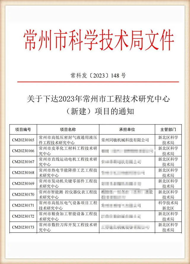
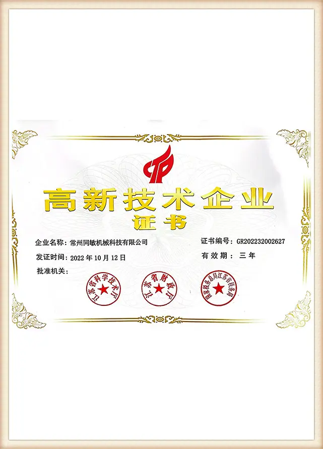
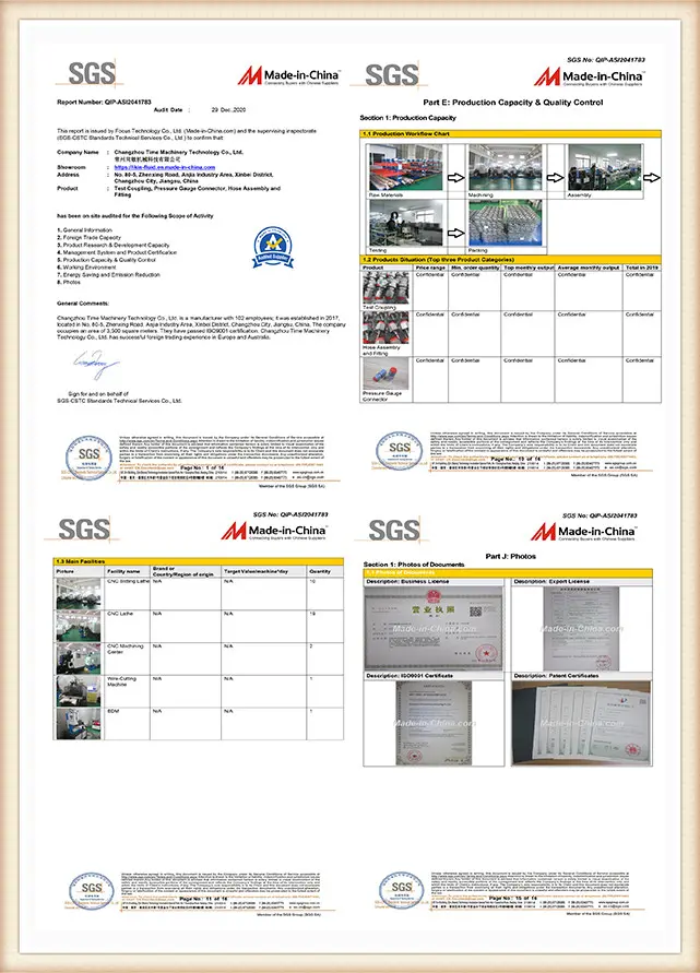
TIME uses a cone-seal design where specified and inspects every hose assembly against the released order before shipment. Our three-year quality warranty is applied under the written order terms.
Input review
We review both ends, bore, finished length, fluid, temperature and working pressure.
Drawing release
TIME prepares a configuration drawing or confirms the selected part reference for buyer approval.
Assembly control
Assembly follows the accepted hose and fitting order specification.
Individual inspection
Each assembly is inspected individually before shipment rather than released from a sample statement alone.
Order handoff
We align marking, packing and requested documents with the written quotation.
Click to enlarge
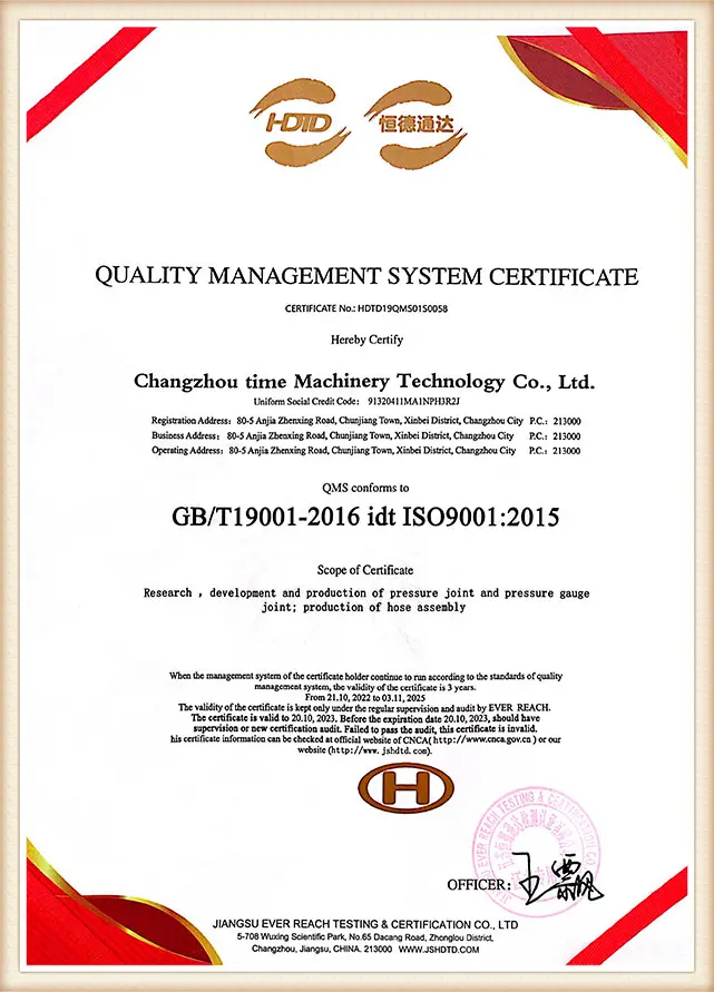
Product drawing
Dimensions, interfaces, material, seal and specified rating belong on the current drawing.
Inspection statement
The quotation can identify the required inspection record format before production.
Marking schedule
Part reference, buyer marking and traceability requests must be agreed for the ordered family.
Warranty scope
The three-year quality warranty applies with the accepted specification and written commercial terms.
“A drawing is not complete for quotation until we can identify both ends, the medium, the working pressure, the connection state and the required length.”
— TIME Hydraulic Engineering Team
Inquiry authority asset
Six-Input Test Hose Brief
The Six-Input Test Hose Brief prevents a visually similar hose from being treated as a confirmed replacement. ISO 4671 separates dimensional methods such as assembly length and through-bore, so the measurement points belong in the brief rather than an assumed catalogue length. Complete all six fields before a product route or drawing is accepted.
01
Machine-side end
Installed test point, port thread, pitch, seat and any mating-part reference
02
Instrument-side end
Pressure gauge, sensor or data-recorder connection and sealing form
03
Hydraulic fluid
Exact medium plus minimum and maximum operating temperature
04
Working condition
Expected working pressure, pressure-test objective and whether connection is depressurized
05
Hose geometry
Required bore family, finished length, measurement points, bend route and access envelope
06
Order evidence
Quantity, marking, drawing format and requested inspection documents
Output A
DN2/DN3, DN4, end-fitting or custom-assembly review route
Output B
Drawing review required until every configuration field is confirmed
Buyer voice reflected
The buyer is not always familiar with the hose or both end forms when replacing an unmarked assembly. One end can look correct while the thread, seal form or crimp system is incompatible. An assembly that is even one inch too short can force re-routing or another purchase.
Complete-Chain Evidence Table
Complete-Chain Product Evidence
One verified component cannot qualify an unverified measurement chain. SAE J517 ties hose-assembly working pressure to the lower applicable rating of the hose and couplings, so TIME reviews the hose, both ends, test point, adapter and instrument connection against one application record. The mistake is allowing a higher-rated component to hide a lower or undocumented limit elsewhere in that chain.
| Chain element | Evidence to record | Why it matters |
|---|---|---|
| Hose core, reinforcement and cover | Part reference, bore, fluid, temperature and working-pressure record | Defines the hose element rather than a family assumption |
| End A | Thread, pitch, seat, material and attachment method | Controls the machine or test-point interface |
| End B | Thread, pitch, seat, material and attachment method | Controls the gauge, sensor or recorder interface |
| Test point or adapter | Current drawing and connection-state scope | Separates connected service from connection-under-pressure permission |
| Instrument | Range, connection, fluid compatibility and calibration status | Supports a meaningful pressure reading |
| Complete assembly | Finished length, through-bore, proof or burst evidence when required | Binds the attached fittings to the hose under the order |
| Lowest confirmed rating | Lowest applicable value among the entered components | Prevents a higher-rated component from masking a lower one |
| Release reference | Approved drawing, revision and written quotation | Keeps the supplied item tied to the reviewed configuration |
- Our hydraulic test hose assemblies serve major equipment manufacturers, hydraulic service teams and distributors.
- Custom lengths and mixed-end configurations can be built after drawing review.
- Product-specific marking and documentation requests are supported when agreed in the quotation.
- Our team separates working pressure, proof test, burst test and impulse evidence rather than treating them as one claim.
- Our product routes include microbore test hose families, DN4 hoses and hydraulic test hose fittings.
Practical comparison
Practical comparison: diagnostic kits from established fluid-power suppliers combine gauges, hoses, test points and adapters because the measurement chain is broader than the hose. TIME supplies and reviews the hose-and-fitting portion against the buyer’s declared chain.
Use boundaries
When a Test Hose Is Not the Right Line
A mini pressure test hose is intended for diagnostic connection and measurement work, not every hydraulic line task. Choose a different route or pause selection when the application below applies.
01
Continuous main-flow service
Use a working hydraulic line sized for required flow rate, pressure loss, impulse duty and machine routing. A diagnostic hose family is not a substitute for that design.
02
Unknown connection geometry
Stop before ordering an adapter from a photo alone. Obtain the drawing or controlled dimensions for thread, pitch, seat and seal.
03
Complete pressure test kit required
Define the required gauge ranges, adapters, test points, case and calibration scope as a kit project. This page covers hydraulic test hoses and fittings, not an assumed complete kit.
04
Unverified connection under pressure
Use the machine procedure and configuration evidence to decide whether connection is allowed. Otherwise isolate and depressurize before changing a connection.
STORED-ENERGY SAFETY
HSE guidance treats hoses and gauges as pressure-system components and calls for suitable equipment, known limits, maintenance and safe isolation. Only trained personnel should follow the machine manufacturer’s procedure; never use a hand to search for a hydraulic leak.
System Resources
Hydraulic Test Hoses & Fittings Tools
Six-Input RFQ Brief
Organize hose connections, fluid, pressure, state, and length to generate a complete drawing review request instantly.
Launch Tool
→
Pressure Rating Checker
Evaluate multiple components in the measurement chain to identify the lowest applicable working pressure limit.
Launch Tool
→
Pressure Converter
Accurately convert MPa, bar, psi, and kPa units specifically for hydraulic test hose order preparation.
Launch Tool
→
Configuration Authorization
Request a Test Hose Drawing Review
Share both connection ends, hydraulic fluid, working pressure, connection state, finished length and quantity. TIME will route the request to DN2/DN3, DN4, end-fitting or custom-assembly review and return a reviewed response within four business days.
KNOWLEDGE BASE
Frequently Asked Questions About Hydraulic Test Hoses
Send both end connections, the exact fluid, working pressure, connection state and finished length. Add temperature, quantity, marking and document requirements for the drawing review.
They identify nominal bore families of 2 mm, 3 mm and 4 mm. Bore alone does not select a hose because reinforcement, length, ends, pressure and route also govern.
No. M16 × 2 states a thread, while the mating geometry, seal, design and qualification scope still need confirmation.
Only when the exact product evidence and machine procedure permit that connection state. ISO 15171-2 gives a public scope for qualifying M16 × 2 couplings, but it is not automatic evidence for every TIME configuration.
Use the lowest applicable confirmed rating among the test point, coupling, hose, hose ends, adapter and instrument. Keep working, proof, burst, impulse and connection-state values as separate evidence fields.
TIME reviews test-coupling, stud, banjo, 24-degree cone, O-ring-seal and pressure-gauge connection routes. Availability depends on the exact interface, material and drawing.
Provide the exact medium and the minimum and maximum temperature. TIME then reviews hose-core, cover, metal and seal options for the ordered configuration.
Yes, after both ends, measurement points, finished length and application conditions are defined. The approved drawing controls the supplied assembly.
There is no fixed minimum for selected DN2, DN3 and DN4 hose assemblies, while end-fitting trial orders can start at 100 pieces. Custom hose prototypes are planned at 10 to 30 business days, and DN4 production at four to six weeks after specification confirmation.
Send the test-point photo or drawing, machine-side thread and seal, instrument end, working pressure, connection state, fluid, temperature, finished length and quantity. Mark the measurement points used for the length.
