
Get in touch with TIME Company

Hydraulic Fluid Sampling Test Points for Controlled Diagnostics
A hydraulic fluid sampling test point supports pressure diagnosis, oil condition monitoring or both—but the installed point and the downstream sampling path need separate proof. Our team manufactures hydraulic test points and hoses, then checks each connection family against the machine interface, operating state, fluid and current drawing.
“For hydraulic pressure testing” describes the market. This page does not authorize proof-pressure testing or turn a diagnostic port into a general sampling process.
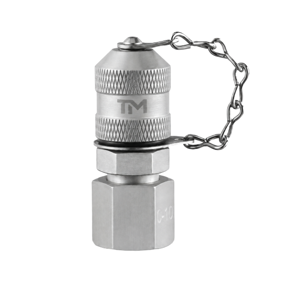
Specifications & Capabilities
Product focus
Hydraulic test points and test hoses only
Sample preparation
Within 3 days
Inspection
100% product inspection
Quality warranty
3 years
Facility
5,000 m² with new workshops under development
Release basis
Current drawing, model and application evidence
Pressure Diagnostics, Fluid Sampling and Dual-Use Selection
01 / Selection Path
Pressure diagnostic path
Use a diagnostic pressure port when the job is to connect a gauge, sensor or test hose and monitor system pressure. The chosen point, mating connector and connection-under-pressure rule all must match current model proof.
02 / Selection Path
Fluid sampling path
Use an oil sampling test point only with a prescribed sample location, pressure-control method, clean container path and repeatable system state. ISO 4021 addresses representative sampling from a working hydraulic system, not product interchangeability.7
03 / Selection Path
Dual-use review path
One installed point may serve more than one maintenance task when every downstream component is independently qualified. We separate the pressure-measurement chain from the fluid-collection chain before we recommend a drawing.
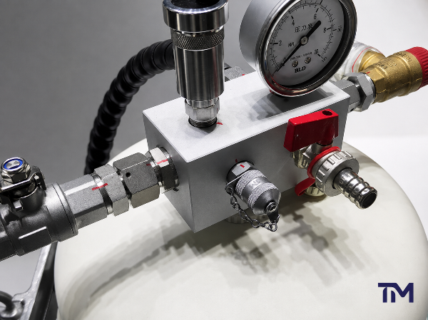
- Proof-pressure testing purposely applies a specified test pressure to determine integrity; it is outside this selection page.
- Routine pressure diagnosis monitors pressure through a defined diagnostic connection, hose and instrument.
- Representative fluid sampling collects oil under controlled location, cleanliness and operating conditions for analysis.
- Field signal: “A convenient port can still return a misleading sample when it sits after a filter or in stagnant oil.”
- Pressure signal: “The installed test point can carry system pressure while the bottle path cannot.”
- Identification signal: “A photo rarely proves both interfaces in one view.”
Unlike a pressure reading, a representative sample depends on location and cleanliness; the two tasks are not interchangeable.
Categorize the task by purpose, system state, sampling location, accessory rating and machine-manual status. Unknown critical inputs fail closed to engineering review; the tool never outputs a TIME model or a universal “safe” result.
Open the Sampling Path Decision Card →Connection Families Without Model Guessing
TIME can check DKO 24-degree, stud, bulkhead, tube or cutting-ring, tee and stainless test-point families. A matching thread is not interchangeable with proof for both sealing interfaces, all dimensions or cross-brand fit.
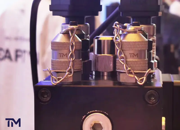
| Connection family | Installation role | Machine-side evidence | Diagnostic-side evidence | Release rule |
|---|---|---|---|---|
| DKO 24° cone | Fits a defined 24-degree tube or connector geometry | Thread, cone, tube size and clearance | Mating coupling geometry and connection state | Current TIME drawing required |
| Stud connection | Threads into a prepared machine port | Thread standard, pitch, port seal and depth | Test-point interface and cap arrangement | Current TIME drawing required |
| Bulkhead connection | Passes through a panel or bracket | Panel thickness, hole, locknut and orientation | Accessible mating space and hose route | Current TIME drawing required |
| Tube / cutting-ring | Integrates with a tube run | Tube outside diameter, cone and ring system | Diagnostic coupling and service clearance | Current TIME drawing required |
| Tee connection | Adds a diagnostic branch to an existing line | Both line ends, branch orientation and envelope | Diagnostic-side geometry and tool access | Current TIME drawing required |
| Stainless variant | Addresses material or environment requirements | Alloy, port geometry and galvanic context | Matching wetted parts and seal evidence | Model and material confirmation required |
M16×2 is not a complete identification
ISO 15171-2 defines a diagnostic-coupling scope around an M16×2 connection end and connection under pressure, but a thread label alone does not identify the machine-side port, seal geometry, accessory chain or supplied TIME model.6
- DKO 24-degree family; dimensions remain drawing-bound.
- Stud family for a defined machine port.
- Bulkhead family for panel-through installation.
- Stainless family; confirm alloy per current model.
Specifications
Materials, Seals and Fluid Compatibility
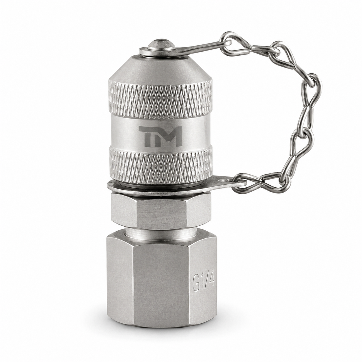
For selection support, review stainless steel test points when the specified connection family matches the drawing and operating conditions.
Body material
Legacy TIME part pages list carbon steel, 304 stainless steel and 316L stainless steel within specific model families. We verify the supplied alloy on current drawing or material statement rather than assuming every geometry is available in every alloy.
Seal material
NBR, FKM and EPDM appear as model-level candidate seal options in old-site records. Choice still depends on fluid chemistry, additive package, temperature range, exposure time and the exact sealing location.
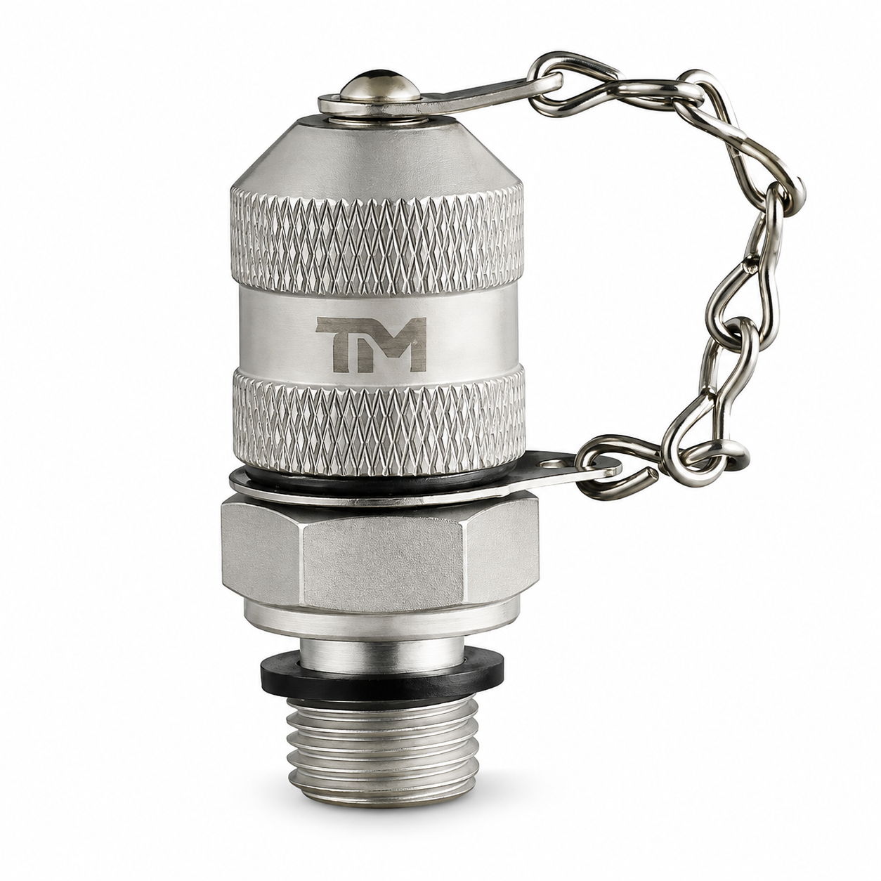
Surface and environment
Carbon-steel legacy pages list zinc and zinc-nickel surface treatments. Corrosion environment, mating metals and required coating proof belong in the enquiry so the finish can be associated with the released part.
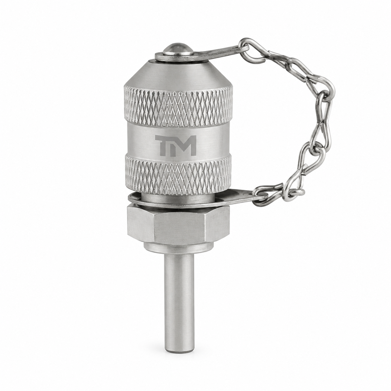
DATA REQ
- State the hydraulic fluid, trade name if available, additives and contamination concern.
- State minimum and maximum operating temperature at the test point.
- Identify every wetted body, seal, hose, reducer, adapter and container interface.
- Ask for the current material declaration for the selected model; ISO 15171-2 scope does not create a universal material default.6
A material list is not a substitute for a model-bound compatibility review. Send the fluid, temperature, environment and requested alloy so TIME can confirm against the current drawing and material statement.
Request a Material ReviewPressure Evidence for the Complete Sample Path
The installed diagnostic pressure port is only one link. We compare every known pressure value and treat the lowest qualified value as the controlling boundary while any unknown critical component remains a release blocker.
| Evidence gate | Required record | Decision effect |
|---|---|---|
| 1 System demand | Maximum operating pressure and transient basis in bar or MPa | Sets the pressure the diagnostic chain must address |
| 2 Installed point | Current model, working-pressure rating and drawing revision | Qualifies only the installed point |
| 3 Connection state | Stopped, depressurized, running or connected under pressure | Controls the permitted connection method; ISO 15171-2 addresses a defined coupling scope, not every product |
| 4 Sampling adapter | Independent working-pressure evidence for the valve or reducer | May become the controlling component |
| 5 Hose and fittings | Rating for each hose, end fitting and intermediate adapter | The smallest qualified value controls the assembled path |
| 6 Container interface | Pressure-reduction arrangement before oil enters a bottle or low-pressure vessel | Separates system pressure from collection pressure |
| 7 Unknown evidence | Blank, unreadable or conflicting rating | Stops release and routes the request to engineering review |
Legacy 630 bar statements stay model-bound
Older TIME product pages list 630 bar for named test-point families. The trade-off is simple: a handy headline number cannot replace separate ratings for the supplied revision, test hose, sampling adapter and bottle path; the current drawing and complete-chain evidence control.
Pressure-to-Sample Boundary Tool
Enter only the ratings you can document. The tool returns the lowest known positive value, names the controlling component and lists every missing field without declaring the application approved.
Representative Sampling Location and Project Support
Active flow
Locate the point where the oil represents the component or circuit question being investigated. ISO 4021 gives preference to extracting a sample from a main flow line in an operating hydraulic system.7
Before or after filtration
A point upstream of a filter can preserve evidence that a downstream point may remove. The correct location depends on whether the maintenance question concerns component wear, circuit cleanliness or filter performance.
Repeatable condition
Record load, speed, temperature, operating duration and sample location. ASTM D8112-26 centres on representativeness and external-contamination control rather than treating any convenient port as equivalent.8
- Flush the stagnant volume in the port, valve, adapter and hose using the written site procedure; published practitioner guidance uses several dead-space volumes as a starting point.5
- Use a clean, suitable sample container and protect the cap and bottle opening from airborne or contact contamination.
- Keep the pressure-reduction route separate from the collection vessel and document every rated component.
- Use the same machine condition and sample method for trend comparison unless the maintenance plan records a controlled change.
System question
A hydraulic oil sample for oil analysis should answer a defined pump, valve or reservoir question. A return line sample port may fit that purpose when its position relative to the filter and target component is recorded.
Collection hardware
Before taking an oil sample, identify the sample valve, pressure gauge, hose, adapter, sampling kit, sample bottle and drain or purge route. Unknown pressure evidence in any item routes the job to review.
Fluid record
Record the hydraulic oil grade, viscosity and target contaminant alongside temperature and operating state. This helps ensure that troubleshooting compares like with like across an industrial condition-monitoring program.
Samples and marking support
TIME prepares samples within 3 days and offers logo customization. Production lead time, order quantity, payment and shipping terms remain specific to the written quotation because no broader commercial commitment was released for this page.
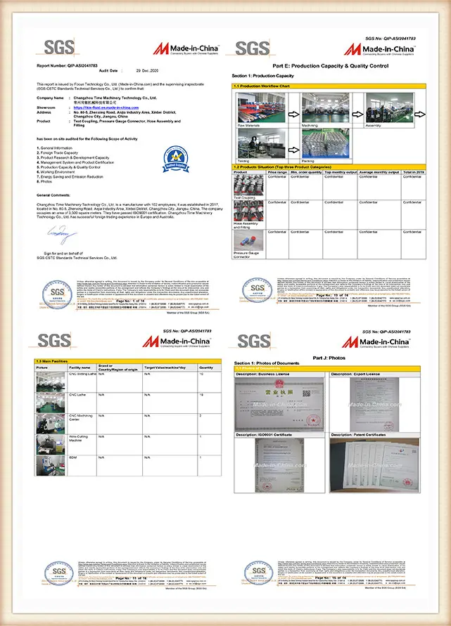
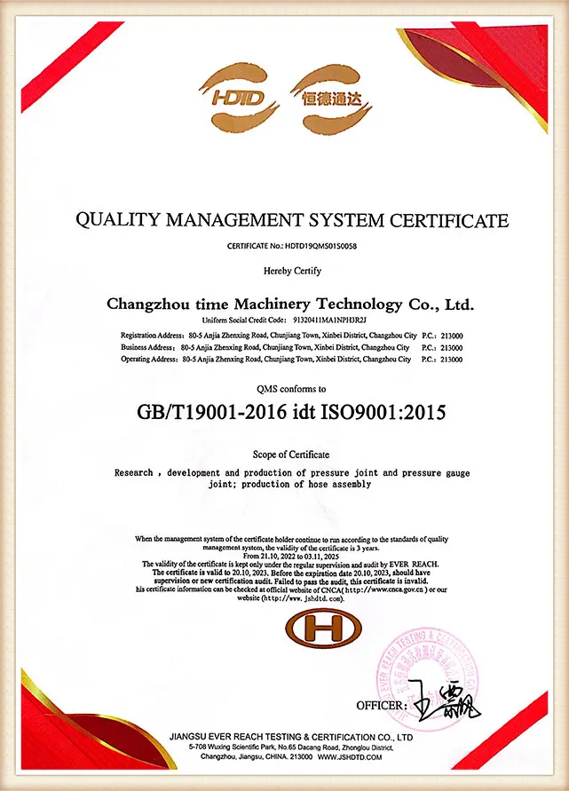
Corporate QA Standards
Quality Assurance, Manufacturing and Inspection
IKIN is the registered trademark and TIME Hydraulic is the operating company. We specialize exclusively in hydraulic test points and test hoses, using cone-seal product designs without turning that architecture into an absolute leakage claim.
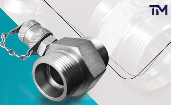
Focused production
TIME operates a 5,000 m² production facility, with new workshops under development. Our China-based production offers a full range of hydraulic test-point connection families and test hose models while keeping drawing review, machining, assembly and testing centred on this product scope.
100% inspection
We inspect every product before packing. The purchase order should still name the required inspection record, acceptance criteria and model revision so the evidence delivered matches the buyer’s release process.
3-year quality warranty
TIME provides a three-year quality warranty. Warranty scope, operating conditions and the accepted drawing should travel with the order record so any nonconformance can be evaluated against the same release basis.
Why the release package matters
A generic product sheet creates a release risk because pressure, material and revision can become detached from the supplied part. TIME resolves that gap through a current drawing, 100% inspection, an order-linked model record and the inspection evidence named by the buyer.
Evidence package to request with a model
01
Current dimensional drawing with model code and revision.
02
Machine-side thread, sealing geometry and installation envelope.
03
Diagnostic-side interface and connection-state instruction.
04
Material and seal statement for the selected fluid and temperature.
05
Working-pressure record for the supplied point and each downstream component.
06
Inspection record named in the enquiry or purchase order.
How We Work Through the Diagnostic-to-Sample Handoff
The Diagnostic-to-Sample Handoff is the release sequence between a diagnostic access point and a controlled sampling route. It keeps interface fit, pressure qualification and sample representativeness visible as separate decisions.
Five sample-quality controls remain after model release
Port location, stagnant-volume flushing, container cleanliness, external-contamination control and a repeatable operating condition decide whether the collected oil can answer the maintenance question. ASTM D8112-26 and ISO 4021 support that separation between hardware access and representative sampling.87
Fluid Sampling Connection Evidence Sheet
Build a copy-ready review sheet covering purpose, state, pressures, both interfaces, fluid, temperature, material, clearance, photo or drawing revision and required documents. All entries stay in your browser.
Build the Fluid Sampling Connection Evidence Sheet →
| Purpose | mark pressure measurement, condition monitoring, fluid sampling or a dual-use request. |
|---|---|
| System state | record stopped, depressurized, running or connection-under-pressure conditions. |
| Installed-point evidence | identify the model, current drawing, working pressure, cap and internal valve arrangement. |
| Sampling-hardware evidence | qualify the valve, pressure reducer, adapter, hose and collection interface independently. |
| Two interfaces | verify machine-side thread and seal separately from the diagnostic or sampling-side coupling. |
| Media evidence | bind fluid, additives, temperature, body material and elastomer to the selected model. |
| Release evidence | close the review with the current drawing revision, material statement, pressure record and requested inspection document. |
Release-status language for the project record
Identified
Use this status only when the purpose, both interfaces, current model drawing, system pressure, connection state, fluid, temperature and downstream ratings are present. It means the evidence set is identifiable; final application approval still follows the buyer’s engineering and maintenance procedure.
Drawing required
Use this status when a family can be recognized but thread pitch, seal geometry, installation envelope, model revision or mating-interface dimensions remain missing. TIME can compare the request with a current drawing after those fields or clear photographs are supplied.
Application review required
Use this status when pressure, fluid compatibility, connection-under-pressure behavior, sample representativeness or a downstream component rating is unknown. The correct next step is an engineering or maintenance review, not a guessed model and not a universal compatibility statement.
Parts We Manufacture and Inspect
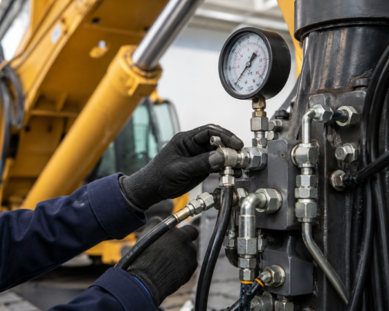
Process
TIME Hydraulic machining and finishing process
Client-owned process image: finishing work.
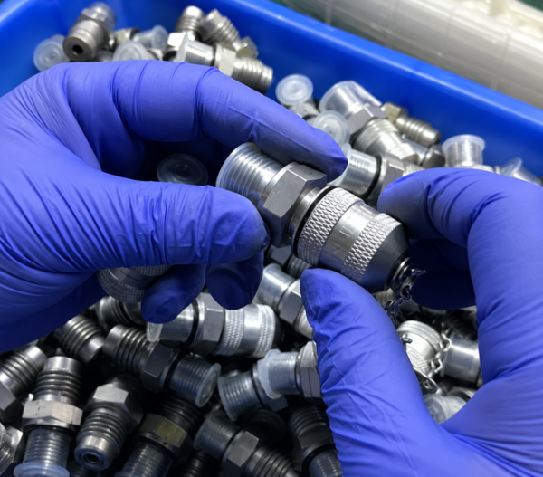
Process
TIME Hydraulic test point assembly process
Client-owned process image: assembly.
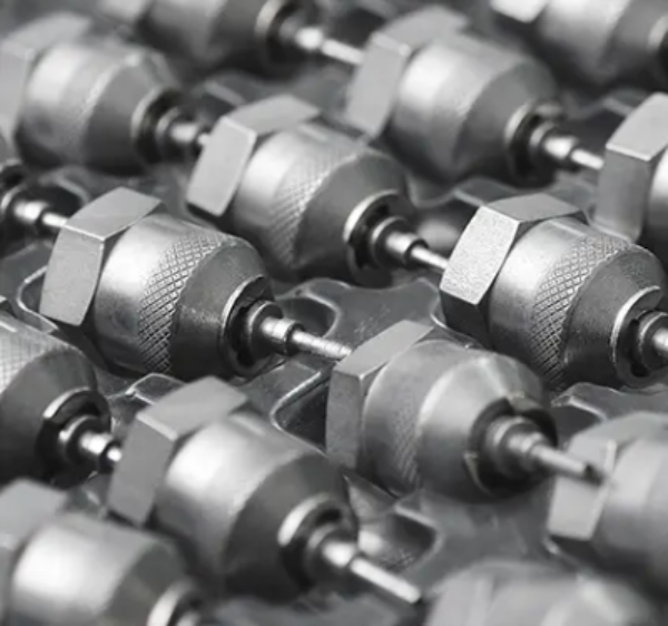
Process
TIME Hydraulic product testing process
Client-owned process image: testing.
Where a Shared Diagnostic-and-Sampling Path Is the Wrong Call
A common access point is useful only when it preserves both system integrity and the sampling objective. The conditions below route the job toward a dedicated point, a pressure-reduction stage or a revised maintenance procedure.
Situation
The easiest port is in a stagnant branch
Why it works against the job
Convenience can produce a sample that does not represent the target component or active circuit.
Better route
Select an active-flow location under ISO 4021 and the machine maintenance plan.7
Situation
The installed point is rated but the bottle path is not
Why it works against the job
A high-pressure point does not qualify a low-pressure adapter, hose or container.
Better route
Add a separately rated pressure-reduction and collection path, or stop for engineering review.
Situation
The thread appears to match but the seal is unknown
Why it works against the job
Thread engagement does not prove seal geometry, insertion depth or mating-interface compatibility.
Better route
Request both-interface photos and a current dimensional drawing before model release.
Situation
The sample is taken after an unknown filter condition
Why it works against the job
Filtration can change the particle population and obscure where contamination originated.
Better route
Choose the point according to the diagnostic question and record its relation to filtration.
Situation
The machine condition changes between samples
Why it works against the job
Trend data loses comparability when load, temperature, run time or procedure changes without a record.
Better route
Use a repeatable operating condition and ASTM D8112-26 contamination controls.8
Fluid Sampling & Diagnostic Test Point Tools
Sampling Path Decision Card
Evaluate and determine the optimal diagnostic route for your hydraulic system. Ensure procedural compliance across all fluid sampling points.
LAUNCH TOOL
Pressure to Sample Boundary Checker
Verify operating pressure limits against specific sampling hardware ratings. Prevent component failure during high-pressure diagnostics.
LAUNCH TOOL
Fluid Sampling Connection Evidence Sheet
Document thread, seal, and mating specifications for system audits. Maintain precise technical records of all diagnostic interfaces.
LAUNCH TOOL
It can support both tasks only when the installed point, connection state and every downstream sampling component are independently qualified. The sampling location and cleanliness procedure must also produce a representative sample.
Do not assume so. Compare documented ratings for the point, adapter or reducer, hose, end fittings and container interface; the lowest qualified value controls, and any unknown value stops release.
No. ISO 15171-2 defines a specific diagnostic-coupling scope around M16×2, but the machine-side port, seal, mating depth, supplied model and downstream accessory still need separate evidence.6
Our team can review DKO 24-degree, stud, bulkhead, tube or cutting-ring, tee and other drawing-defined families. Send the thread, sealing geometry, installation envelope and a clear photo or drawing; we will not select from a family name alone.
Consider stainless when corrosion environment, cleaning chemistry, fluid compatibility or buyer material policy requires it. Confirm 304 or 316L at the model and drawing level rather than applying an old-site alloy label to the entire family.
The written machine or laboratory procedure controls. Published practitioner guidance often starts with several internal dead-space volumes, but the required volume depends on the port, valve, hose, operating condition and contamination objective.5
Send the machine-side thread and seal, diagnostic-side interface, system state, maximum operating pressure, fluid, temperature, material requirement, installation clearance and current photo or drawing revision. Add the inspection and material documents your release process requires.
Yes. TIME prepares samples within 3 days, and logo customization is available; state the selected model, drawing revision and application evidence in the request.
No. Proof-pressure testing requires a defined component, test pressure, procedure, containment, instrumentation and acceptance criteria; this page is a selection guide for diagnostic access and controlled fluid sampling.
