Get in touch with TIME Company


Test Point Adapters & Tee Connections are easy to misidentify because one assembled connection can contain several different interfaces. One familiar M16x2 diagnostic end may sit on an adapter with a completely different machine-side stud. Adding an inline tee creates two line connections plus a diagnostic branch. Thread engagement may occur even though the intended seal, pressure permission, fluid compatibility, or drawing revision is still unknown.
This guide is for maintenance technicians, engineers, and technical buyers who need to make that connection reviewable before selecting or installing a model. It explains how to name the full connection, read the drawing, separate thread evidence from seal evidence, control pressure-state assumptions, commission the joint, and preserve a useful maintenance record. It doesn’t publish a universal torque, promise cross-brand interchangeability, or replace the machine and component instructions.
Updated August 2026. Standards are identified by edition or revision so readers can distinguish a current scope record from a generic fitting label.
Safety boundary
Installing, tightening, removing, or repairing a permanent hydraulic connection is servicing work. Apply the site’s energy-control procedure, isolate hazardous energy, relieve or restrain stored pressure, and continue verification where pressure can reaccumulate. Never use a hand to search for a pressurized leak. The UK Health and Safety Executive’s hydraulic injection bulletin notes anecdotal evidence that injection injury may occur at pressures as low as 7 bar.
Never use a hand to search for a pressurized leak. The UK Health and Safety Executive’s hydraulic injection bulletin notes anecdotal evidence that injection injury may occur at pressures as low as 7 bar.
Name the Complete Hydraulic Adapter or Tee Connection
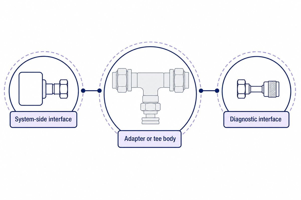
Hydraulic test point adapters join a system-side port or fitting to a diagnostic test connection. Hydraulic test tees add the test branch while preserving a line path between two other connections. Those definitions describe functions, not complete specifications. Every actual joint includes each pressure-retaining interface, sealing surface, mating part, and document that defines the installed state.
Start with an adapter-or-tee interface record. Do not reduce the component to “M16 test point,” “JIC tee,” or another shop label. Those names can be useful search terms, but they leave out the evidence needed to inspect its pressure-retaining boundaries. For broader routing before interface-level work, use the broader test-point choice across interface and pressure factors.
| Record field | Evidence to capture | What the field does not prove |
|---|---|---|
| System-side interface | Port or line standard, thread, stud end, gender, seat, and seal | That the diagnostic end is correct |
| Adapter or tee body | Exact part identity, geometry, material, orientation, and drawing revision | That a similar-looking body is interchangeable |
| Diagnostic interface | Coupling family, mating connector, cap, seal, and permitted connection state | The rating of the complete test chain |
| Search wording | Evidence source | Decision consequence |
|---|---|---|
| Hydraulic test point fittings or test point fittings | Exact part identity and all mating drawings | A broad label cannot release a joint |
| Gauge adapters and pressure gauge ports | Port, diagnostic end, instrument limit, and seal record | Gauge access does not prove full-chain suitability |
| Hydraulic systems and hydraulic system pressure | Machine circuit and authorized operating-state record | System wording is not a component rating |
| Hydraulic pressure or hydraulic pressure testing | Separate working, test, residual, and connection states | One pressure value cannot answer every state |
| Test-point adapters and secure connections | Released drawings, seal geometry, instructions, and witness record | The adjective “secure” is not acceptance evidence |
| Oil sampling and pressure monitoring | Purpose-specific connector, fluid scope, hose, and instrument procedure | A diagnostic purpose does not define the installed interfaces |
| Adapter kit | Item-by-item identity and permitted mating combinations | Kit membership does not prove interchangeability |
| Carbon steel or NPT | Body specification, finish, exact thread form, seal path, and fluid scope | Material or thread shorthand remains incomplete |
| Machinery reliability, flow control, and downtime | Site procedure for controlling and venting pressure plus revision-controlled observations | Business impact cannot substitute for technical acceptance |
For an inline tee, identify both line ends independently. Two ends that share a nominal size may still use different seats, swivel arrangements, or sealing elements. Also record which branch is the diagnostic connection and how the installed orientation affects access, hose routing, and inspection.
Review boundaries change with the component. Direct adapters have two principal interfaces; inline tees have three branches, each able to introduce its own thread, seat, seal, alignment, and document requirement. This guide stops at those adapter-or-tee boundaries. Downstream hoses, instruments, and measurement routes require their own evidence. Treating the diagnostic branch as an accessory while reviewing only the through-line can leave the most frequently handled interface outside change control.
Ask not “Which fitting does this resemble?” but “Can every pressure-retaining transition be named and tied to current evidence?” If one transition is unknown, mark that field unknown. Do not fill it from the opposite end of the body, a catalog photograph, or a part used on another machine. Such discipline gives engineering and procurement a reviewable problem instead of a confident but untraceable shop description.
Read the Drawing Before Touching the Fitting
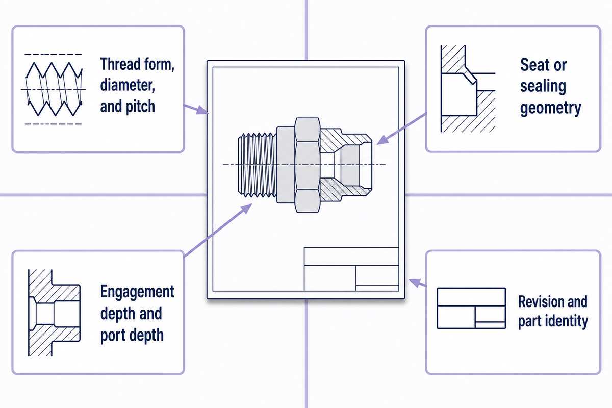
Current released drawings separate dimensions that spoken terminology often merges. Read the component drawing together with the machine port or line drawing. If one side is missing, the connection remains incomplete even when the available drawing looks precise. Mechanical thread retention still doesn’t identify the primary seal.
| Drawing evidence type | Why it matters | Stop condition |
|---|---|---|
| Thread form, diameter, and pitch | Defines engagement evidence | Only a nominal label or visual estimate is available |
| Gender and stud or port standard | Identifies the intended mating family | A thread chart is being used as the complete specification |
| Seat or sealing geometry | Shows where the fluid boundary should form | The drawing omits the mating surface |
| Seal identity and location | Connects material and condition to the correct groove or face | An O-ring or sealant is being added by assumption |
| Engagement depth and port depth | Prevents bottoming, insufficient engagement, or seat interference | Length is being inferred from a photograph |
| Body orientation and envelope | Protects access and prevents side load | The hose or connector must be forced into position |
| Material and finish | Supports environmental and assembly review | Compatibility is inferred from color alone |
| Revision and part identity | Binds every field to the actual component | The installed marking and current drawing cannot be matched |
An official ISO 15171-2 scope record illustrates why this separation matters. It lists an M16x2 diagnostic end and specific system-facing stud-end routes, including M14x1.5, G 1/4, and 7/16-20 UNF under named port standards. That is bounded geometry evidence. It does not define every tee body, every adapter combination, or the installed machine port simply because one end matches the diagnostic family.
Read the evidence in a fixed order. First match the permanent marking or traceable part identity to the released drawing. Next compare the machine-side and diagnostic-side interfaces separately. Then trace the intended fluid boundary: the retaining thread, primary seal, mating surface, and any secondary containment shouldn’t be collapsed into one field. Finally, compare orientation, access, and the complete assembly instruction with the installed location. Use the machine-side thread and seal identification workflow for the separate thread-identification route.
Distributor descriptions and thread charts can help locate candidate documents, but they sit below the component drawing, the mating-port drawing, and the machine procedure. Likewise, dimensions taken from installed parts are observations, not automatically nominal requirements. Wear, coating, damage, measurement access, and the wrong datum can all make a precise-looking measurement answer the wrong question. Record the tool, datum, observed value, and uncertainty when a measurement is used to support escalation.
Thread Fit Is Not Seal Proof
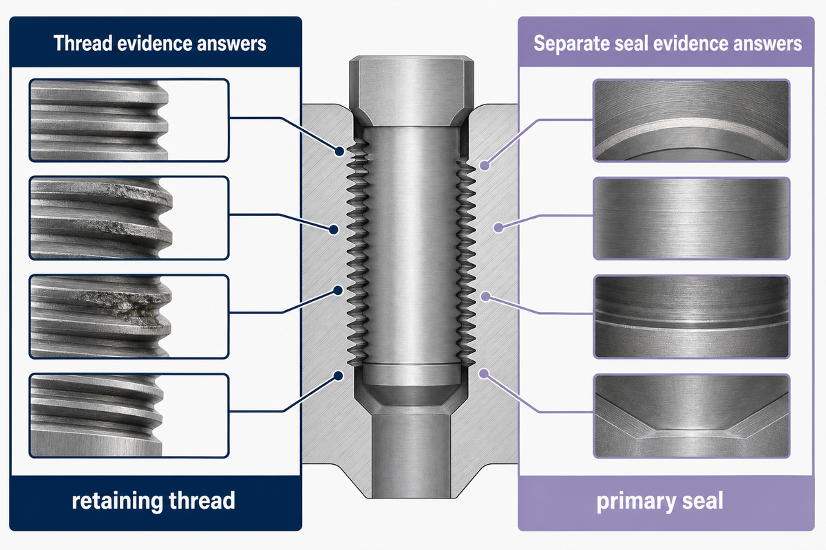
Thread Fits; Seal Evidence Decides is the central rule of this guide. Threads may retain a component, position a seat, compress a seal, or form part of a tapered sealing path. They do not all perform the same function. Successful hand engagement proves only that some dimensions can engage; it does not prove that the intended sealing faces meet, that an elastomer has the right material and compression, or that the assembly is approved for the fluid and pressure state.
| Question | Thread evidence answers | Separate seal evidence answers |
|---|---|---|
| Will the parts engage? | Form, diameter, pitch, gender, and permitted engagement | Whether the actual sealing surfaces will meet correctly |
| Where is pressure contained? | Sometimes at the thread, often elsewhere | Seat, cone, face, O-ring, bonded seal, or documented alternative |
| How is the joint tightened? | Identifies the bounded fitting family | Exact instruction, lubrication/coating state, material, and reaction point |
| Will it remain suitable? | Cannot answer alone | Fluid, temperature, pressure cycle, contamination, surface condition, and seal material |
Seal appearance can help form questions, but it is not a complete diagnosis. Parker’s O-ring failure guidance distinguishes patterns such as extrusion, installation damage, abrasion, compression set, and chemical degradation. Chewed downstream edges may be consistent with extrusion; nicks may be consistent with installation damage. Record the observation and compare it with the exact groove, pressure, material, and assembly evidence before assigning a cause.
The same caution applies to torque. SAE AS5148A addresses assembly, installation, and torque values for a bounded family of flareless and straight-thread fittings. Its existence disproves the idea that fitting-family torque data never exists. It does not create one torque for every test point adapter, tee, cone seat, O-ring port, taper thread, material, finish, or manufacturer design.
Separate Pressure States and Standards Scope
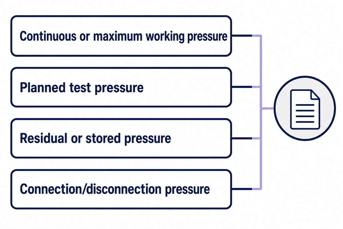
Pressure is not one field. Working pressure describes operation within a component’s documented conditions. A pressure test belongs to a defined test method and authorized procedure. Residual pressure is energy that may remain after the pump stops. Connection or disconnection pressure answers whether a designated diagnostic coupling may be operated in a particular state. One number must not be substituted for another.
| Pressure field | Evidence source | Common misuse |
|---|---|---|
| Continuous or maximum working pressure | Exact component and assembly documentation | Treating it as permission to connect or service under pressure |
| Planned test pressure | Authorized test procedure and complete chain limits | Inventing a multiplier from another product family |
| Residual or stored pressure | Energy-control procedure and verified machine state | Assuming pump-off means pressure-free |
| Connection/disconnection pressure | Exact coupling standard and manufacturer instruction | Borrowing the higher working-pressure rating |
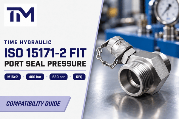
The official ISO records make this distinction visible. ISO 15171-1:1999 is titled for a diagnostic coupling not intended for connection under pressure. ISO 15171-2:2016 covers an M16x2 end that may be connected under pressure without tools up to 40 MPa (400 bar), while also stating maximum working pressure up to 63 MPa (630 bar), dependent on materials, design, working conditions, and application. The 63 MPa figure is not a 63 MPa hot-connection permission. Use the M16x2 connection-under-pressure scope analysis when that standard family needs a deeper review.
SAE J1502_202205 defines the male half of another diagnostic route using M14x1.5 or 9/16-18 straight-thread stud ends and states 42 MPa working pressure, again with application-dependent limits. Its public scope is for mineral-based hydraulic fluid and named SAE J1116 machine classes; it also states that dimensional conformance alone does not guarantee rated performance and that each manufacturer should test. Standards establish their own scopes; they do not certify an unidentified component or guarantee that two brands’ parts form an approved assembly.
| Source and bounded subject | Published boundary | What must remain separate |
|---|---|---|
| ISO 15171-1:1999 diagnostic coupling family | Title states not intended for connection under pressure | Working rating, machine state, and identity of the installed product |
| ISO 15171-2:2016 M16x2 diagnostic end | Up to 40 MPa (400 bar; about 5,802 psi) for connection under pressure within scope | The separate 63 MPa (630 bar; about 9,137 psi) maximum working-pressure statement |
| SAE J1502_202205 diagnostic stud-end family | 42 MPa (about 6,092 psi) working pressure, application-dependent | Connection-state permission and the rating of other components in the chain |
| HSE hydraulic injection safety bulletin | Anecdotal evidence suggests injury may occur at pressure as low as 7 bar (about 102 psi) | A product rating or a threshold below which leak searching by hand becomes acceptable |
The conversions to psi above are rounded arithmetic for United States readers; the cited records express their controlling values in MPa or bar. Before making a release decision, return to the exact current source, the manufacturer document, and the machine procedure. The smallest applicable limit in the complete chain may belong to the adapter, tee, diagnostic coupling, test hose, instrument, port, seal, or operating method.
ISO 15171-2 keeps 40 MPa (400 bar) connection pressure separate from 63 MPa (630 bar) maximum working pressure. SAE J1502 lists 42 MPa for its bounded family, while HSE notes anecdotal evidence of injection injury at 7 bar. Those values answer different questions and cannot be merged into one category limit. For the separate downstream measurement-state decision, use the site’s complete-route pressure reading integrity guide.
Use the 10-Step Evidence-before-Wrench Sequence
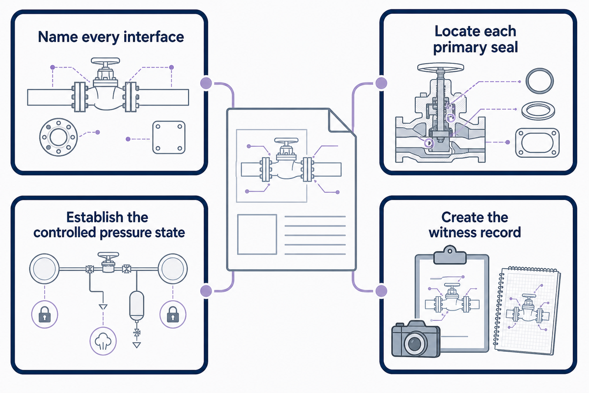
Use The Evidence-before-Wrench Sequence as a release method, not an installation substitute. It tells the reviewer when enough evidence exists to open the controlling procedure, and when work must stop.
- Identify the machine and circuit location. Confirm why the point exists and which documented pressure condition it’s intended to observe.
- Name every interface. Record both ends of an adapter, all three branches of a tee, the diagnostic coupling, and the mating hose or instrument.
- Bind identity to current documents. Match part markings, released drawings, standards, machine instructions, and revisions. Keep unknowns visible.
- Locate each primary seal. Separate the thread’s retaining role from the cone, face, seat, O-ring, bonded seal, taper, or other documented sealing boundary.
- Verify material and working-fluid compatibility. Do not infer elastomer compatibility from body material. ISO 15171-2’s public scope is for mineral-oil systems and calls for supplier-purchaser agreement for other fluids.
- Establish the controlled pressure state. Apply the site’s energy-control procedure for servicing. Confirm isolation and how stored energy will be relieved, restrained, and monitored.
- Check for reaccumulation. OSHA’s stored-energy guidance requires continued verification where stored energy can build again. One-time gauge readings aren’t permanent proof.
- Confirm the exact assembly instruction. Use the correct tool, reaction point, tightening method, cleanliness practice, and orientation. Generic torque charts aren’t a fallback.
- Define commissioning and stop conditions. Name who may energize the circuit, the authorized state, observation method, abnormal conditions, and response owner.
- Create the witness record. Capture identity, revision, installation source, pressure state, observer, date, and unresolved items before release.
Commissioning belongs inside this sequence, not after it. Before energization, name the person who controls the test, the expected operating state, the observation location, the instrument range, and the stop response. The witness should be able to distinguish “no visible abnormality under the authorized condition” from “leak-free for all future service.” The first statement is a bounded observation; the second is an unsupported lifetime conclusion.
Record the state in which each observation was made. A joint viewed while isolated, a joint observed during a controlled test, and a diagnostic coupling operated under a source-permitted connection pressure are three different evidence events. If pressure can rebuild, define how verification continues and who owns the response. This keeps a one-time reading from becoming a permanent safety assumption.
Stop before installation when:
- the mating drawing or sealing surface is unknown;
- the pressure figure is present but connection-state permission is absent;
- the fluid or seal material falls outside documented compatibility;
- the installation instruction belongs to a different fitting family;
- isolation can’t be verified or pressure can reaccumulate without control; or
- the installed part can’t be matched to the released revision.
Inspect the Five Fields That Describe the Seal
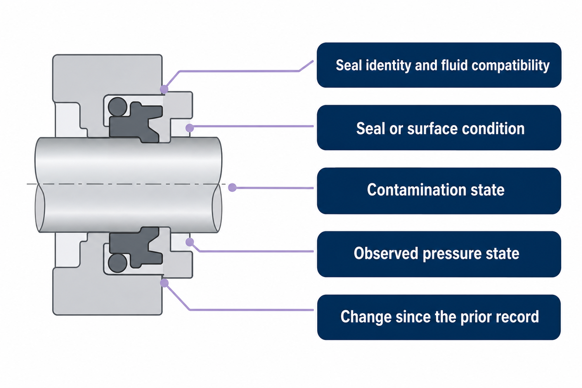
Pass/fail boxes hide too much. Use The Five-Field Seal Record to keep observations tied to the exact interface and prevent a later reviewer from treating a wet surface as a complete root-cause diagnosis.
Five fields to record
- Seal identity and fluid compatibility: seal type, material when documented, location, actual fluid, temperature range, and evidence source.
- Seal or surface condition: cut, flattening, extrusion pattern, abrasion, corrosion, dent, scratch, deformation, or no visible defect.
- Contamination state: debris, damaged cap, exposed connector, residue, cleaning method, and whether any measured cleanliness evidence exists.
- Observed pressure state: isolated, residual, operating, authorized test, connection, or unknown, plus how the state was established.
- Change since the prior record: new, stable, recurrent, worsening, moved, replaced, or not comparable because the part/revision changed.
Photographs are useful when they show scale, orientation, and the exact interface, but they don’t replace a drawing or acceptance criterion. Record where fluid appeared, then inspect the entire connection chain under the controlling procedure. Fluid can travel along a body, thread, hose, or adjacent surface before it becomes visible. The emergence point narrows the investigation; it doesn’t prove the damaged part.
Fluid scope belongs in the seal record because the ISO 15171-2 catalog scope addresses mineral-oil-based systems and calls for agreement when other fluids are used. That wording does not approve a particular elastomer; it shows why “body material known” and “seal compatibility verified” are separate fields.
Diagnose Symptoms Without Guessing the Failed Part
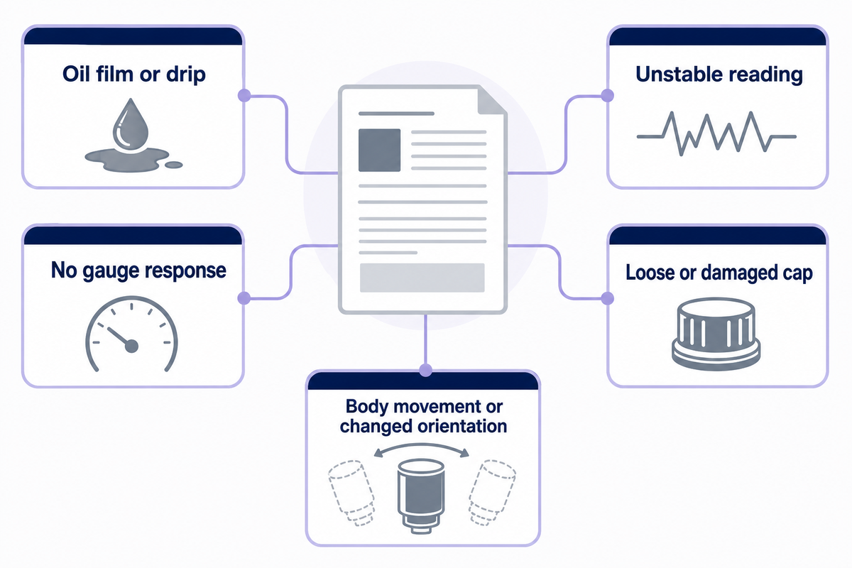
Troubleshooting should move from a symptom to evidence, not from a symptom to a purchase. Keep the system in the required safe state and follow the machine procedure. The table below gives investigation fields, not repair instructions.
| Symptom | Immediate controlled response | Evidence to inspect | What it does not prove |
|---|---|---|---|
| Oil film or drip | Do not tighten or touch under pressure; isolate and escalate | Emergence point, nearby joints, seal record, orientation, pressure state, recent work | That the visible part is the cause |
| No gauge response | Stop if the procedure or limits are uncertain | Correct circuit point, valve state, coupling engagement, hose, instrument, range, blockage | That the system has zero pressure |
| Unstable reading | Preserve the test conditions and avoid random part changes | Operating state, connection stability, trapped gas, hose route/length, instrument response, actual transient | That the adapter or pump alone is faulty |
| Loose or damaged cap | Protect the point and review contamination exposure | Cap/retention feature, interface condition, debris, handling history | That the internal valve or seal failed |
| Body movement or changed orientation | Remove from release decisions until the mounting boundary is reviewed | Reaction point, tightening evidence, support, side load, nearby service work | That re-tightening is the correct response |
Transient measurements need one extra boundary. A 2023 peer-reviewed measuring-hose study compared hydraulic measuring hoses of 0.4 m, 0.8 m, and 1.5 m and found hose-length-dependent frequency response and transient pressure distortion under the tested conditions. That finding is a reason to stop at the adapter-or-tee diagnosis: dynamic measurement validity belongs to the complete route and its governing method, not to a universal correction factor in this article. Use the complete-route pressure reading integrity guide linked above when that is the actual question.
Maintain a Revision-Controlled Connection Record
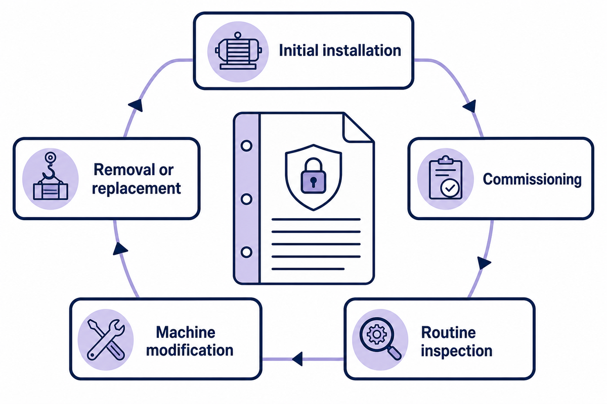
Each hydraulic connection record should survive staff changes, replacement events, and machine modifications. Store enough information for another reviewer to identify what was installed and distinguish a changed component from a changed observation.
| Lifecycle event | Minimum evidence | Owner |
|---|---|---|
| Initial installation | Part and drawing revision, all interfaces, seals, instructions, orientation, witness, date | Engineering/maintenance per site process |
| Commissioning | Authorized pressure state, observation method, result, abnormal condition, release decision | Authorized test owner |
| Routine inspection | Five-field seal record, cap/access condition, comparison with prior record | Maintenance |
| Machine modification | Changed port, line, guard, hose route, fluid, operating state, and revised approval | Change-control owner |
| Removal or replacement | Reason, as-found condition, removed identity, replacement identity, unresolved cause, disposition | Engineering/procurement/maintenance as assigned |
Do not invent a universal replacement interval. Use the machine maintenance plan, component instructions, environment, duty cycle, and condition evidence. Trigger an additional review after leakage, impact, cap loss, contamination, corrosion, unexpected movement, abnormal readings, or work on adjacent lines.
The OSHA hazardous-energy control overview frames servicing around an energy-control program. Use that authority only for the site’s energy-control record; it does not set an adapter or tee replacement interval.
Revision control should preserve both the before and after state. When a tee is replaced, keep the removed part identity, as-found seal condition, reason for change, replacement identity, drawing revision, installation source, and commissioning observation in one linked record. If the suspected cause remains unresolved, say so. Symptom removal after replacement does not by itself prove which interface failed.
Periodic review is also a document check. Confirm that the installed marking remains legible, protective hardware is present, the recorded fluid and machine configuration still apply, and the referenced instructions have not been superseded. A date of manufacture does not prove that the current configuration remains approved. A physical joint can appear unchanged while its approval basis becomes obsolete after a fluid conversion, port modification, hose reroute, or procedure revision.
Prepare a Documented Engineering Handoff
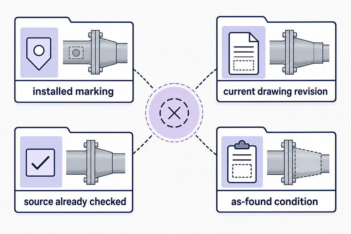
Escalation should identify the exact adapter-or-tee boundary that remains unresolved, not recreate a general product-selection package or a complete measurement trace. Send the evidence that lets the responsible engineer decide whether interface review can continue:
- the installed marking, current drawing revision, any applicable assembly and installation instruction, and photographs of the unresolved mating boundary;
- the specific thread, seat, seal, material, pressure-state, or orientation field that cannot be verified;
- the source already checked and why it does not close the evidence gap; and
- the as-found condition, explicitly marked unknown wherever evidence is absent.
This escalation note is not a request for quotation and does not select a model. Once the adapter-or-tee evidence gap is resolved, the dedicated product page owns product-family, configuration-completeness, and commercial review.
Move to Product-Level Review Without Repeating the Solution Page
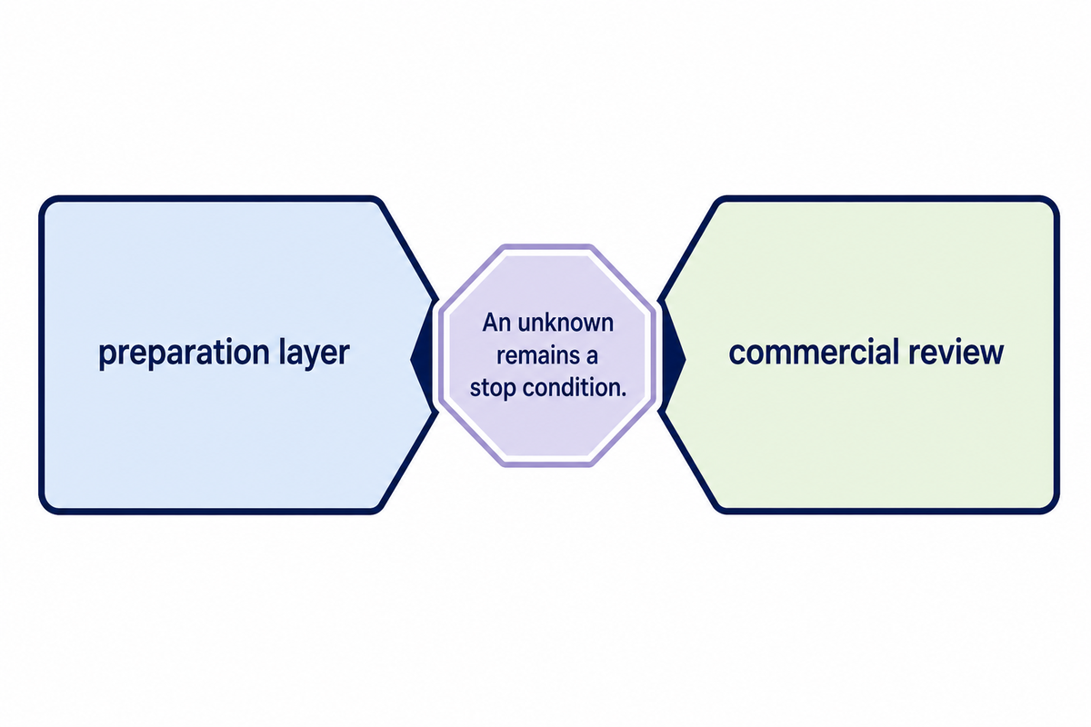
Once the evidence package is complete, use the dedicated test point adapters solution page for product-family and model-level evaluation. That page owns the commercial review. This guide remains the preparation layer: it helps you identify interfaces, pressure states, sealing evidence, inspection fields, and unresolved risks before asking any supplier to evaluate a configuration.
If required evidence is still unknown, don’t use the product page to guess around the gap. Return to the drawing, machine record, responsible engineer, or exact component documentation. An unknown remains a stop condition, not a familiar value.
Frequently Asked Questions
What are hydraulic test fittings?
Hydraulic test fittings provide a defined diagnostic access route, but the category name does not specify the system-side interface, diagnostic end, seal, pressure state, or document revision.
Hydraulic test fittings create a documented access route for a gauge, transducer, sampling device, or diagnostic hose. The term can describe an installed test point, diagnostic coupling, gauge-port adapter, inline test tee, or mating connector. Specify the system-side interface, fitting body, diagnostic interface, seal, mating equipment, and document revision. A category name alone doesn’t prove pressure limits, fluid compatibility, connection-state permission, or interchangeability. That evidence set is the minimum basis for comparing a candidate with the installed circuit.
Why can a hydraulic adapter leak when the thread fits?
Thread engagement can coexist with a wrong or damaged cone, face, seat, or elastomeric seal because the retaining thread and primary sealing surface may perform different functions.
The thread may retain or position the fitting while a separate O-ring, cone, face, seat, or bonded seal contains the fluid. Parts can engage yet leave the wrong sealing geometry, damaged surface, incorrect elastomer, contamination, poor alignment, insufficient engagement, or an assembly condition outside the instructions. Record where fluid appears, isolate the system under the controlling site procedure, and inspect the complete joint. Don’t assume that more torque or thread sealant is the answer.
Can an M16x2 test point be connected under pressure?
The M16x2 label alone does not grant pressure-state permission; within ISO 15171-2, the 40 MPa (400 bar) connection boundary remains separate from the 63 MPa (630 bar) maximum working statement.
ISO 15171-2 gives a 40 MPa connection-under-pressure boundary for a specific M16x2 coupling family. It does not identify an unknown product or override its instructions and machine procedure. ISO 15171-1 is titled for a coupling not intended for connection under pressure. Verify the exact family, documents, pressure state, and complete chain.
What should be recorded after installing a hydraulic test tee?
Record all three tee interfaces, every seal, the controlling documents, final orientation, pressure state, commissioning observation, witness, date, and every unresolved field that still requires review.
Record tee identity, drawing revision, two line interfaces, diagnostic branch, each seal, final orientation, controlling instruction, pressure state, commissioning observation, witness, and date. Add the Five-Field Seal Record and photograph the installed orientation. Keep unresolved fields visible for later review.
When should a test point adapter or tee be removed from service?
Removal or continued service must follow the exact machine and component acceptance criteria; leakage, damage, unreadable identity, obsolete evidence, or changed service conditions require controlled review.
Use the exact machine and component criteria. Leakage, damaged sealing surfaces, corrosion, deformation, movement, contamination, unreadable identity, obsolete drawings, changed fluid, or operation outside documented scope requires controlled review. Record the as-found condition and let the responsible procedure assign repair, replacement, or disposition.
Editorial Scope Boundary
This article separates documented interface and maintenance preparation from product-level selection because the same broad phrase also supports the site’s commercial solution page. It uses public standard scopes, safety guidance, and peer-reviewed evidence without treating any of them as certification of an unidentified adapter, tee, assembly, or brand. Product identity remains a document-level review.
References & Sources
- ISO 15171-1:1999 official scope record International Organization for Standardization
- ISO 15171-2:2016 official scope record International Organization for Standardization
- SAE J1502_202205 SAE International
- SAE AS5148A SAE International
- Control of Hazardous Energy United States Occupational Safety and Health Administration
- Hydraulic injection injury safety bulletin United Kingdom Health and Safety Executive
- Influence of hydraulic measuring-hose length on dynamic measurements peer-reviewed article in PubMed Central
Standards are cited for their published scope. They don’t certify an unidentified product or complete installed connection.