Get in touch with TIME Company


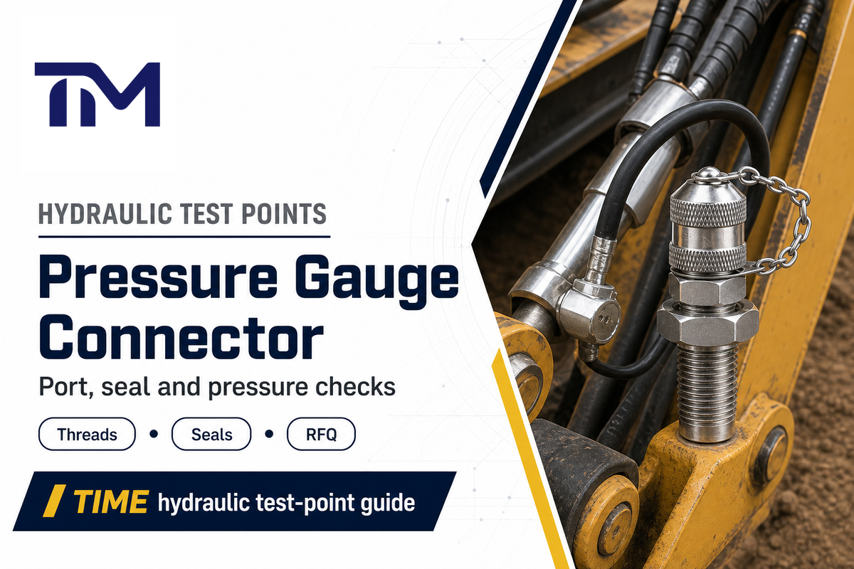
A pressure gauge connector selection guide for hydraulic test points shouldn’t start with a generic adapter chart. It should start with the measurement job: what pressure you need to read, where the port is, which diagnostic coupling family is involved, and whether the complete gauge-to-port chain can safely handle the pressure, movement, temperature, fluid, and inspection requirements.
TIME Hydraulic manufactures hydraulic test points and hydraulic test hoses, not pressure gauges. That narrower scope matters. The correct pressure gauge connector may be a direct adapter, a test hose lead, an M16 x 2 diagnostic coupling assembly, a microbore hose, or a service kit. The wrong choice can still look right on the drawing and still fail in the field.
Quick Answer
Select a pressure gauge connector by checking the measurement objective, diagnostic coupling family, port thread and geometry, gauge or hose interface, seal form, lowest-rated pressure component, impulse or flexing need, hose bore and routing, media and ambient temperature, fluid and cleanliness fit, field containment, and documentation proof. Don’t treat thread name, nominal bore, or a single pressure rating as the whole decision.
Port-to-Gauge 12-Point Diagnostic Chain
For selection support, review pressure gauge connector product range when the specified connection family matches the drawing and operating conditions.
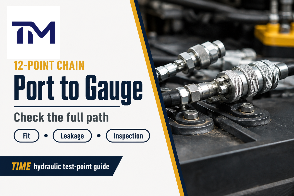
The practical way to choose a hydraulic pressure gauge adapter is to work from the port toward the instrument. Every item below can block the assembly, create leakage, distort the reading, or weaken incoming inspection if it’s left vague in the purchase request.
| Check Type | What to Confirm | Wrong Choice Creates | Evidence to Send |
|---|---|---|---|
| 1. Measurement objective | Steady-state check, average pressure reading, or pulsating/transient diagnosis. | A valid-looking reading that is wrong for the application. | Pressure objective, gauge range, accuracy, calibration status. |
| 2. Diagnostic coupling family | M16 x 2 diagnostic coupling, flush-face quick coupling, or another family. | Unsafe live-connection assumption or non-interchangeable parts. | Coupling family, required standard, fluid scope. |
| 3. Port thread and geometry | M16 x 2, BSP, NPT, JIC, metric, stud end, pitch, and port face. | Cross-threading, binding, or no seal even when the thread starts. | Port photo, drawing, thread gauge result. |
| 4. Gauge or hose interface | Gauge inlet, test hose end, adapter, and coupling standard/size. | Adapter stack-up and poor gauge position. | Gauge model, hose end drawing, target layout. |
| 5. Seal form | Cone seat, O-ring, sealing ring, poppet, washer, or designed face seal. | Leak path or contamination from improvised sealing. | Fluid, pressure, temperature, seal material preference. |
| 6. Complete-chain pressure limit | Lowest-rated hose, connector, gauge, adapter, coupling, and valve. | Overrated assembly because one weak component is hidden. | System max pressure plus all component ratings. |
| 7. Impulse/flexing qualification | Static spot check, pulsating pressure, flexing route, or spike exposure. | Static pressure proof mistaken for impulse endurance. | Required impulse/flexing test method and criteria. |
| 8. Hose bore and routing | DN2, DN3, DN4, free length, bend, abrasion, storage, replacement interval. | Slow response, strain at the fitting, or premature hose failure. | Route sketch, free length, bore preference. |
| 9. Temperature | Media temperature and ambient environment. | Seal hardening, swelling, or pressure rating used outside the envelope. | Media and ambient range. |
| 10. Material/fluid/cleanliness | Steel or stainless steel, elastomer, mineral oil or other fluid, cleanliness need. | Corrosion, chemical resistance problem, seal damage, or particle ingress. | Fluid type, material requirement, cleanliness/inspection requirement. |
| 11. Field containment | Hose whip, expelled fittings, guards/restraints, exclusion zone, trained assembly. | Injury risk during exposed testing. | Risk-control procedure and inspection program. |
| 12. Documentation proof | Certificates, pressure-test report, method, criteria, sample scope, drawing approval. | Incoming inspection cannot verify what was purchased. | Material certificate, pressure test report, drawing confirmation. |
Direct Gauge Adapter, Test Hose Lead, or Custom Assembly?
For selection support, review 45° and 90° pressure gauge connectors when the specified connection family matches the drawing and operating conditions.
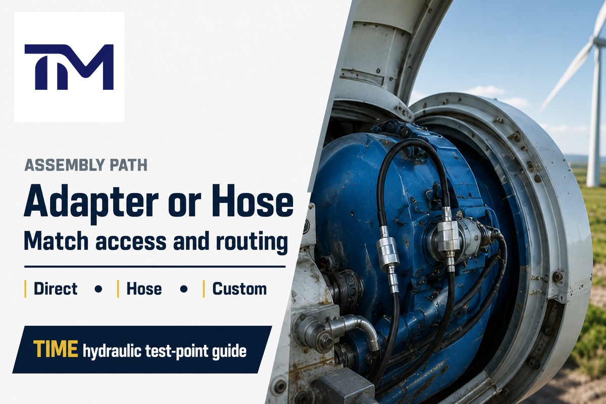
A direct pressure gauge adapter is useful when the test point is reachable, the gauge can be mounted without strain, and the pressure check is short and stable. It’s the simplest path, but it isn’t automatically the safest or most repeatable one.
A test hose lead moves the pressure gauge away from a cramped or hot port, reduces awkward installation, and can make repeated diagnostic work faster. For hard-to-reach mobile equipment, test benches, or service teams, the hose is often the part that turns a theoretical connection into a usable pressure measurement setup.
A custom assembly is better when the buyer already knows the required hose length, bore, end fittings, pressure class, seal form, and inspection documents. TIME product evidence lists custom hydraulic test hose assemblies in DN2 and DN4, M16 x 2 diagnostic coupling options, metric stud ends, O-ring seals, sealing rings, pipe thread stud ends, instrument ends, and bulkhead or panel connections.
For mixed-equipment service work, a kit can be more practical than a single fixed matrix. A service kit may include pressure gauges, test hose, adapters, reducing adapters, and multiple couplings. Use the 12-point chain to define what must be in the kit, not to pretend one connector path fits every machine.
Selection shortcut
- Choose a direct adapter when the port is accessible and the gauge position is safe.
- Choose a test hose lead when the gauge should be read away from heat, motion, or restricted access.
- Choose a custom assembly when length, bore, ends, pressure rating, and documents must be controlled before production.
- Choose a kit when a distributor or maintenance team supports multiple equipment families.
Useful TIME internal references: hydraulic test hose end fittings for connector and thread choices, and custom hydraulic test hose assemblies for assembly-level review.
Thread Standards and Port Fit for Hydraulic Test Points
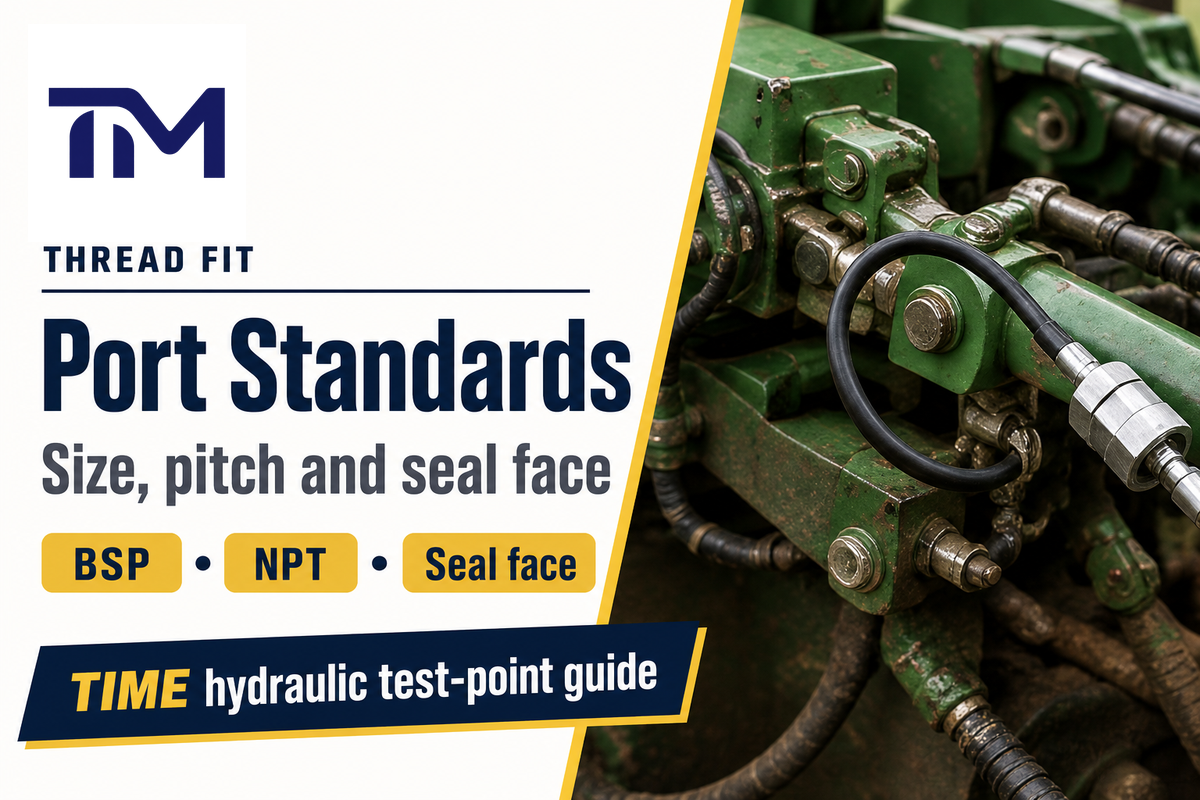
Thread labels aren’t enough. Buyers often search for NPT, BSP, JIC, metric, BSPP, DKO 24 degree male cone, or M16 x 2 and assume the connector is solved. In practice, the thread, pitch, port geometry, seal face, and mating gauge or hose end must all match.
The distinction is especially important for pipe threads. ISO 228-1 covers pipe threads where pressure-tight joints are not made on the threads. That means a standardized thread family can still require the correct sealing face or gasket design. ASME B1.20.1 is relevant for general-purpose inch pipe thread context, but the buyer still has to confirm the actual port and seal requirement.
What thread is a pressure gauge?
There’s no single pressure gauge thread. A pressure gauge or test hose assembly may use NPT, BSP, metric, JIC, M16 x 2, or a process-connection style chosen for the instrument and application. For hydraulic test points, start with the machine port and diagnostic coupling family, then confirm the gauge inlet or hose end. If the gauge is digital, mechanical, or mounted through a panel, that doesn’t remove the thread and seal check.
Procurement note
Ask for a port photo and drawing before confirming a pressure gauge fitting. A thread that starts by hand can still be wrong if the seal face, pitch, or stud-end geometry is mismatched.
How to Filter Generic Pressure Gauge Selection Advice
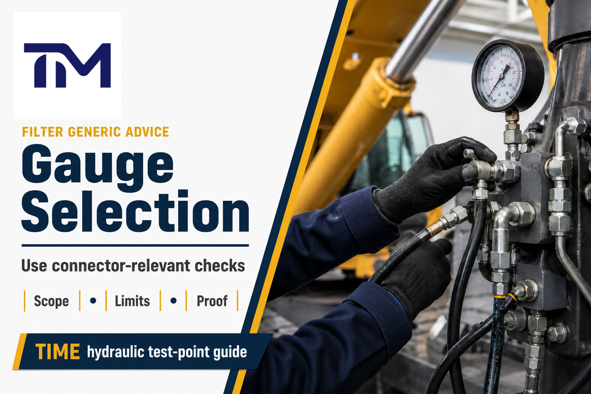
Many pressure gauge selection articles discuss a process connection on the instrument side: flange, clamp, tube, diaphragm pressure gauge, sanitary service, pharmaceutical lines, steam, viscous media, crystallize risk, and hygiene requirements. Those terms are useful as an overview of different types of pressure measurement, but they can distract from a hydraulic test point purchase.
For TIME’s scope, the industrial question is narrower: choose the right pressure gauge connector, hose, and fitting path for high pressure hydraulic test work. The suitable solution must withstand the working pressure, resist corrosive or chemical exposure when the fluid or environment demands it, preserve sealing performance, and eliminate avoidable leakage and contamination.
| Category | Generic Pressure Gauge Selection Term | Hydraulic Test Point Interpretation |
|---|---|---|
| Instrument connection | process connection, flange, clamp | Confirm the gauge inlet and adapter interface, but do not ignore the diagnostic coupling. |
| Gauge body | diaphragm pressure gauge, digital gauge, mechanical instrument | Useful for gauge choice; separate from TIME’s connector and hose manufacturing scope. |
| Media behavior | steam, viscous fluid, crystallize risk | State the actual hydraulic fluid, temperature, cleanliness, and seal material requirement. |
| Industry language | sanitary, pharmaceutical, hygiene | Do not import these assumptions unless the hydraulic application really needs them. |
| Material language | alloy, stainless steel, corrosion, chemical resistance | Select the right steel, stainless steel, NBR, FKM, or other material by fluid and environment. |
| Pressure language | pressure range, type of pressure, pressure and temperature | Record steady pressure, high pressure spikes, pulsation, and temperature together. |
| Installation language | easy to disassemble, easy installation, options available | Check whether disassembly, repeated service, and safe gauge position are actually required. |
| Cost language | low-cost, commonly used, service life | Prefer the lowest lifecycle risk, not the cheapest adapter that causes rework. |
| Compliance language | code, industry standards, specific industry, different industries | Ask which standard, method, and acceptance criteria apply to this hydraulic assembly. |
When selecting the proper connector path, use the broader pressure gauge selection vocabulary only as a screening layer. The RFQ still has to land on a specific hydraulic fitting, hose bore, seal, pressure class, and inspection document.
A buyer reading a generic article about choosing the right pressure gauge should still ask a narrower question: what connector path will ensure compatibility and durability in this hydraulic test point? A widely used adapter may be reliable in one application and unsuitable in another. Consider when selecting the connector whether “choosing the right” gauge has already been separated from choosing the right hose, fitting, seal, and test-point coupling.
Seal Form and Leakage Risk

Leakage usually begins where the specification is too broad. “1/4 NPT adapter” or “M16 connector” may describe part of the connection, but it doesn’t define the sealing method. Cone seats, O-rings, sealing rings, poppets, washers, and designed face seals behave differently under pressure, temperature, vibration, disassembly, and contamination.
| Hidden Bottleneck | Field Symptom | Buyer Action |
|---|---|---|
| Wrong seal face | Leak even when the thread size appears correct. | Send the port drawing and required seal form. |
| Wrong elastomer | Swelling, hardening, or chemical resistance failure. | State fluid type, temperature, and material preference. |
| Tape used where a designed seal is required | Blocked passages, particle contamination, or unstable readings. | Specify the designed seal instead of field improvisation. |
| Worn cap or dirty test point | Debris enters the pressure measurement path. | Include cap condition, cleanliness expectation, and inspection method. |
TIME’s stated product position is cone-seal, zero-leakage design, 100% inspection, and a 3-year quality warranty. Use that as an RFQ requirement, not as permission to skip the seal form, fluid, and temperature checks.
Pressure Class, Measurement Objective, and Lowest-Rated Components
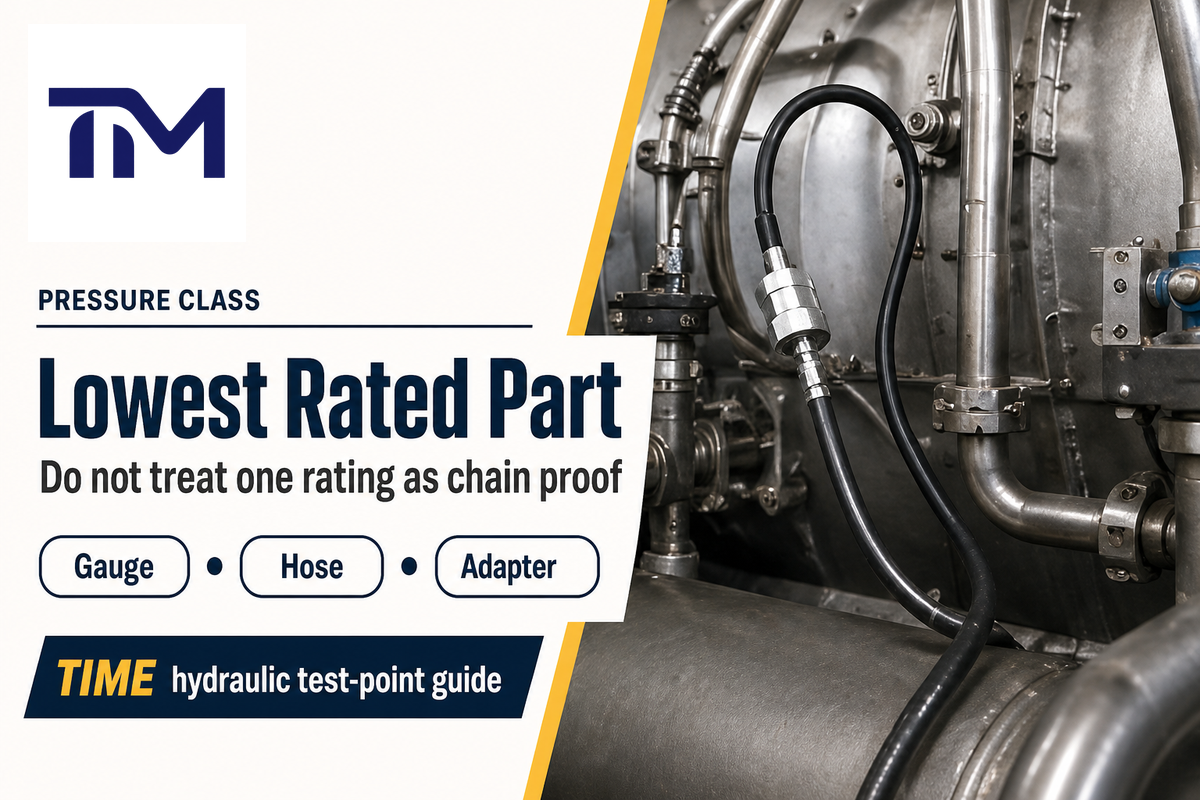
Pressure class should be checked as an assembled chain, not as a headline connector rating. TIME first-party pages list maximum working pressure up to 63 MPa, 630 bar, and some pages list connect-under-pressure capability up to 40 MPa, 400 bar for relevant diagnostic assemblies. Those facts help define available product scope, but the purchase request still needs the system pressure, spike condition, gauge rating, hose rating, adapter rating, and coupling rating.
Standards boundaries make this point sharper. ISO 15171-2:2016 is specifically about M16 x 2 hydraulic diagnostic couplings for connection under pressure without tools up to 40 MPa, 400 bar, with use up to 63 MPa, 630 bar depending on materials, design, working conditions, and application. It also states a mineral-oil scope, with other fluids requiring supplier-purchaser agreement. That does not prove any supplier’s conformity unless the supplier provides the relevant documentation.
By contrast, ISO 16028:2023 covers flush-face quick-action hydraulic couplings for 10 MPa, 100 bar, to 31.5 MPa, 315 bar, depending on size and states that those couplings are not designed to connect or disconnect under pressure. The practical warning is simple: do not use “quick coupling” as a synonym for “live diagnostic test point.”
Measurement objective also matters. ISO 9110-1 and ISO 9110-2 provide hydraulic fluid power measurement-technique context for pressure measurement and average steady-state pressure. If the machine has pressure spikes or high-vibration conditions, a stable-looking average reading may not be the only concern. Gauge protection, snubbers, valves, or a different diagnostic setup may be needed.
Use numeric checkpoints in the quote instead of vague pressure language: M16 x 2 diagnostic coupling, M14 x 1.5 stud end, G 1/4 stud end, 7/16-20 UNF stud end, 40 MPa, 400 bar, 5,802 psi, 63 MPa, 630 bar, 9,137 psi, 10 MPa, 100 bar, 31.5 MPa, 315 bar, 1.5 MPa, 3 MPa, DN4 4 mm inside diameter, and 5,000 m2 factory-scale context where the supplier is using facility evidence in the commercial discussion.
Lowest-rated-component rule
The safe working pressure of a pressure gauge connector setup is limited by the lowest-rated part in the chain: port, adapter, diagnostic coupling, test hose, gauge connection, valve, and any intermediate fitting. Record each rating before issuing the order.
DN2, DN3, and DN4 Hose Pairing Beyond Bore and Length
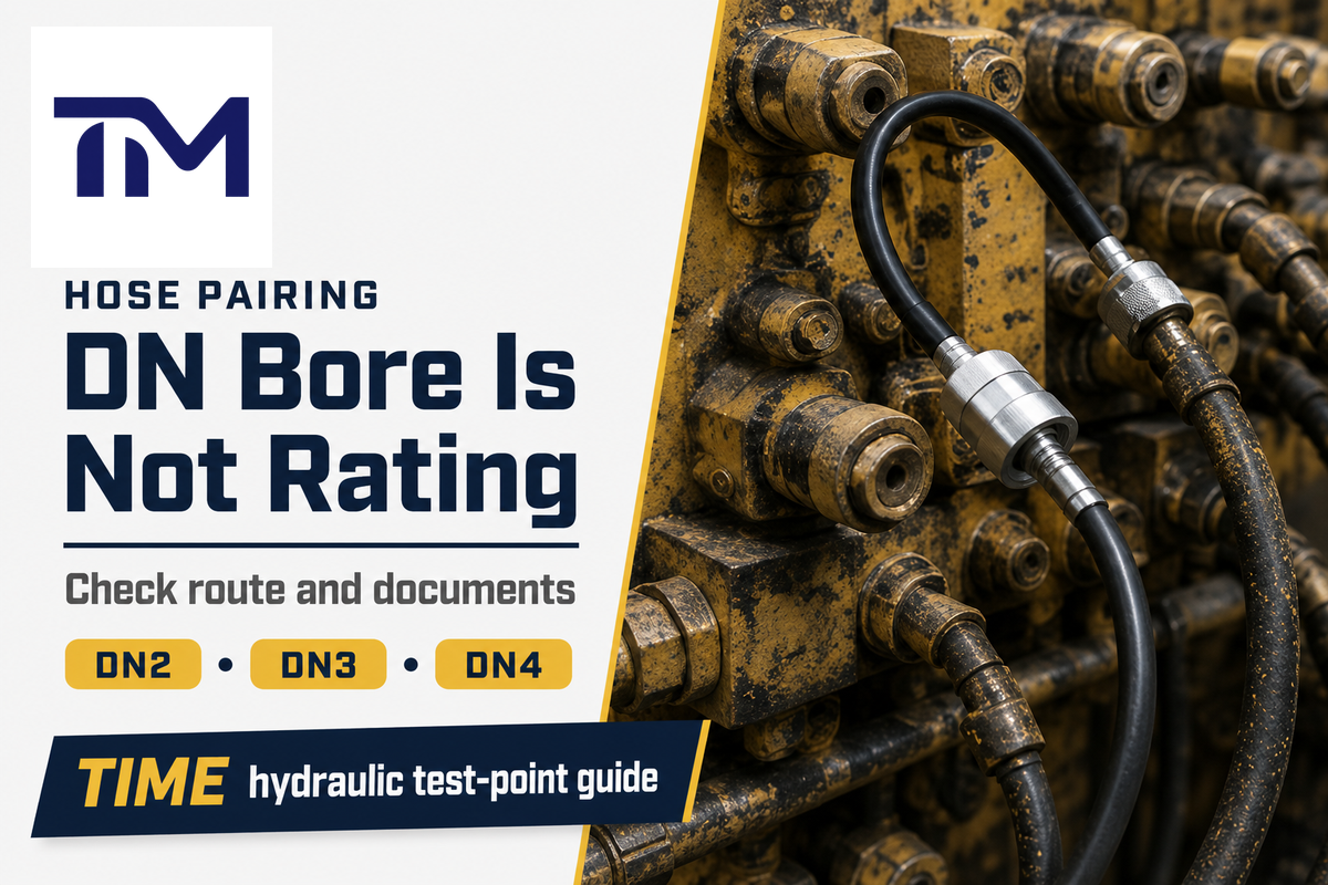
DN size is a hose bore decision, not a pressure shortcut. TIME product evidence lists DN2 and DN3 microbore hydraulic test hoses with M16 x 2 test coupling options, JIC 37 degree connection, DKO 24 degree male cone, metric compression fitting, BSPP fittings, NPT fittings, maximum working pressure of 63 MPa, and connect-under-pressure limit of 40 MPa for the listed scope.
TIME’s DN4 hydraulic test hose page lists DN4 as a 4 mm inside-diameter, high-flow test point assembly with connection types including BSP, NPT, JIC, and metric, and maximum working pressure up to 630 bar. Use those page facts to define the available product family, then confirm the final assembly rating with drawings and inspection documents.
| Hose Path | Best Fit | Do Not Assume | Send With RFQ |
|---|---|---|---|
| DN2/DN3 microbore | Restricted routing, compact diagnostic access, lower internal volume. | That small bore automatically means higher pressure capability. | Route sketch, bend constraints, end fittings, pressure and impulse need. |
| DN4 | Larger bore and higher-flow diagnostic setups. | That larger bore solves gauge vibration, spike, or safety issues by itself. | Length, pressure, port type, gauge interface, field position, documents. |
For pulsating service, ask whether the required proof is static pressure, impulse without flexing, or impulse with flexing. ISO 6803 describes hydraulic-pressure impulse testing without flexing for rubber or plastics hydraulic hose assemblies subject to pulsating pressures, including high-pressure testing above 3 MPa and low-pressure testing from 1.5 MPa to 3 MPa. ISO 6802 covers hydraulic impulse testing with flexing in the same high and low impulse pressure bands. A generic pressure test report is not the same as impulse/flexing qualification.
Buyer Role Checklist
Different stakeholders carry different risks. A useful pressure gauge connector guide should turn the same technical facts into role-specific actions.
Maintenance Engineer
- Confirm safe gauge position.
- Check cap condition and port contamination.
- Record recurring diagnostic points and hose route.
Distributor Sourcing
- Ask for model coverage and drawing confirmation.
- Separate direct adapters, test hoses, and kits.
- Make certificates and inspection wording part of the quote.
Private-Label Manager
- Standardize repeatable part families.
- Confirm logo, packaging, and warranty terms.
- Keep TIME’s hydraulic test point and hose scope clear.
Quality Engineer
- Request material certificates and pressure test reports.
- Check cleanliness, traceability, and inspection criteria.
- Confirm sample scope, method, and acceptance criteria.
Common Failure Modes When the Connector Looks Correct
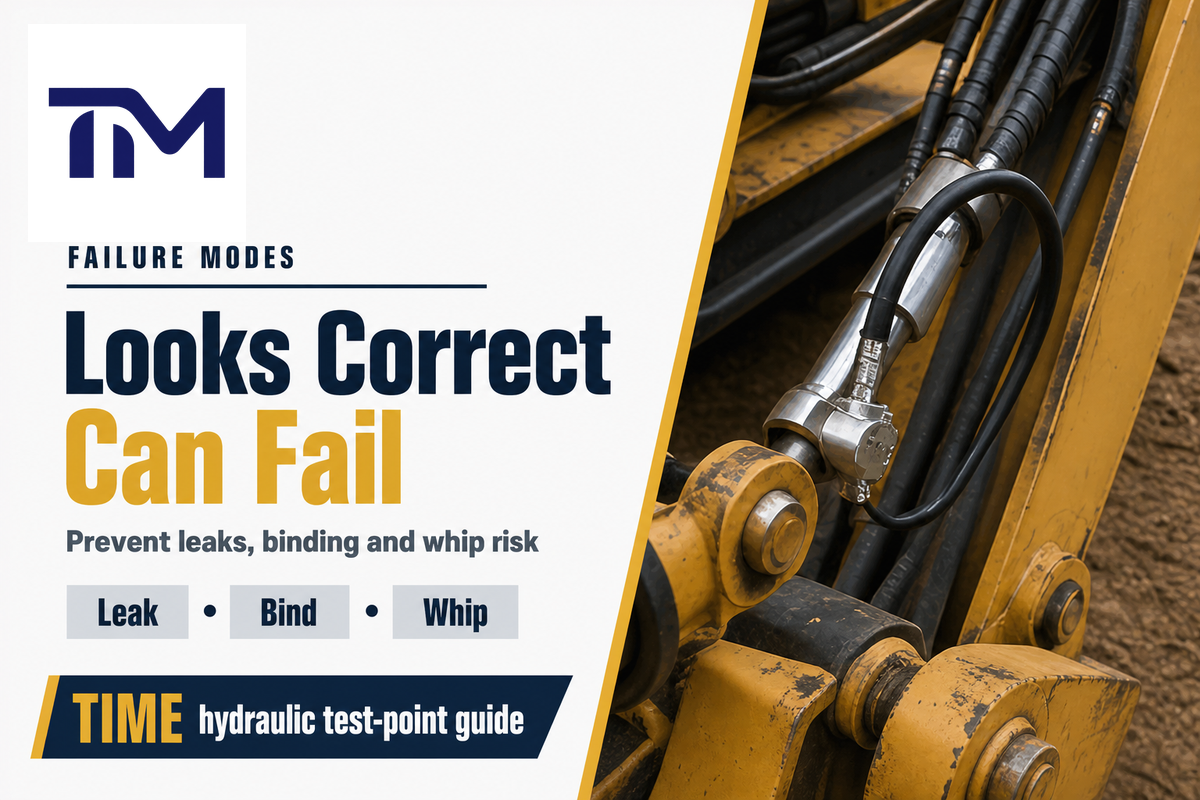
The most expensive connector mistakes aren’t always obvious at receiving. Many are “almost right” parts that pass a quick visual check and fail only when installed, pressurized, or audited.
| Failure Mode | Field Symptom | Likely Cause | Prevention Evidence |
|---|---|---|---|
| Fits but leaks | Oil at the port or gauge connection. | Wrong seal face, worn cap, wrong elastomer. | Seal form, fluid, temperature, drawing. |
| Thread starts but binds | Part tightens early or damages the port. | Pitch, thread family, or stud-end mismatch. | Thread gauge, pitch, port photo. |
| Gauge reads slowly | Lagging response during a pressure check. | Bore, hose length, restriction, clogged passage. | Hose bore, route, cleanliness check. |
| Needle vibrates or spikes | Unstable reading or damaged instrument. | Pulsation, high-vibration, no gauge protection. | Measurement objective, spike condition, protection requirement. |
| One component is underrated | Assembly rating lower than expected. | Only connector headline rating was checked. | All component ratings in the chain. |
| Wrong live-connection assumption | Buyer expects connection under pressure from a generic quick coupling. | ISO 15171-2-style diagnostic coupling confused with ISO 16028-style quick coupling. | Coupling family, standard, supplier confirmation. |
| Static proof used for dynamic service | Failure during pulsation or flexing. | Pressure test report did not cover impulse/flexing. | ISO 6803 or ISO 6802 type requirement if applicable. |
| Temperature missing | Seal or hose material behaves differently in service. | Pressure rating considered without media and ambient range. | Media temperature, ambient temperature, material preference. |
| Incoming inspection cannot verify order | Receiving team lacks evidence to accept or reject parts. | Report lacks standard, method, criteria, or sample scope. | Material certificate, pressure report, inspection criteria. |
| Field containment missing | Exposed worker risk during hydraulic testing. | No guard, restraint, exclusion zone, training, or hose inspection program. | Procedure, trained assembly, visual inspection, storage and age control. |
OSHA citation evidence on high-pressure hydraulic fluid testing describes struck-by hazards where hose assemblies can blow apart, fittings can be thrown, and loose hose can flail or whip with great force. It also points to controls such as guards/restraints, visual inspection, functional tests, hose storage, age control, and trained assembly.
RFQ Checklist: What to Send TIME Before Production
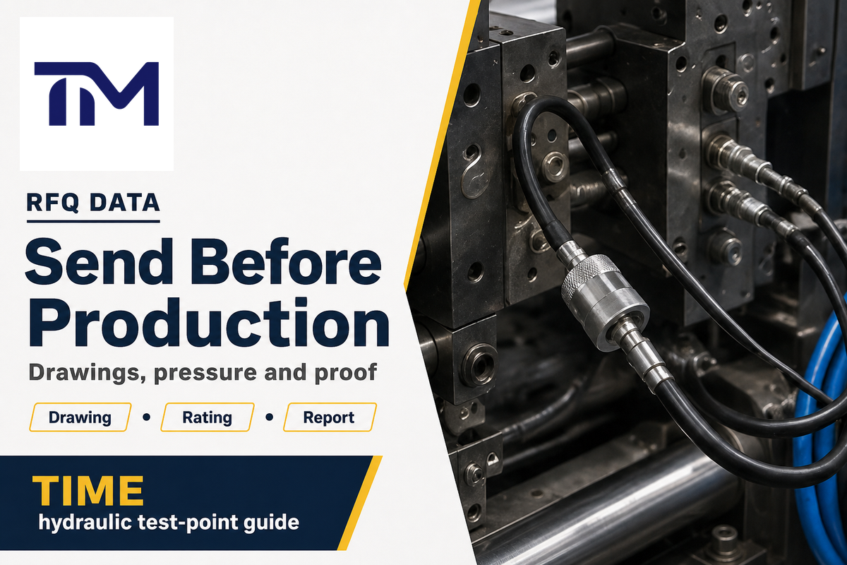
A clean RFQ saves more time than a long email thread. Send the connector team enough information to choose the right pressure gauge connector, test hose, or assembly without guessing.
Measurement-chain RFQ checklist
- Measurement objective: steady reading, average pressure, troubleshooting, pulsation, or repeated service check.
- Port photo, machine drawing, thread family, thread size, pitch, and seal face.
- Required diagnostic coupling family or standard, if the project specifies one.
- Gauge model, inlet thread, pressure range, accuracy, calibration status, and whether the instrument is mechanical or digital.
- System maximum pressure, expected spikes, and all component ratings already known.
- Fluid type, cleanliness requirement, media temperature, and ambient temperature.
- Hose route, free length, bend constraints, abrasion risk, bore preference, and replacement/storage context.
- Seal requirement, material preference, stainless steel or zinc-plated steel preference, NBR/FKM or other elastomer need.
- Pressure-test report requirement: standard or method, test pressure, performance criteria, and sample scope.
- Impulse/flexing-test requirement if the assembly will see pulsating pressure or flexing.
- Field containment procedure, stored-energy boundary, guard/restraint need, and trained assembly requirement.
- Packaging, logo, private-label, documentation language, delivery target, and warranty expectation.
TIME Hydraulic focuses exclusively on hydraulic test points and hoses. The company operates with the IKIN registered trademark, ISO and SGS certification positioning, a 5,000 m2 production facility, new workshops under development, 100% inspection, cone-seal zero-leakage design focus, and a 3-year quality warranty according to the user-provided brand brief and first-party product evidence.
Need the connector path checked before ordering?
Send TIME your port photo, drawing, pressure range, hose route, and document requirements. The team can review whether you need a direct adapter, test hose lead, microbore hose, DN4 assembly, or custom connector set.
FAQ
What thread is most common for a hydraulic pressure gauge connector?
View Answer
There is no universal thread. Hydraulic pressure gauge connector projects commonly involve NPT, BSP, metric, JIC, M16 x 2, BSPP, DKO 24 degree male cone, or other machine-specific connections. The safer rule is to confirm thread family, size, pitch, port geometry, and seal face before choosing the adapter or test hose fitting. A buyer should also check whether the pressure-tight seal is made on the thread, on an O-ring, on a cone seat, on a washer, or on another designed face.
How do I connect a pressure gauge to a hydraulic test point?
View Answer
Start with the test point port and diagnostic coupling family, then select the gauge interface, seal form, pressure rating, and hose path. If the port is hard to reach or unsafe for direct gauge mounting, use a test hose lead so the gauge can be read from a better position. Always confirm stored-energy and field-containment procedures before testing.
Is a pressure gauge adapter the same as a hydraulic test hose fitting?
View Answer
No. A pressure gauge adapter usually solves one connection interface, such as gauge inlet to port thread. A hydraulic test hose fitting is part of a hose assembly that also has bore, length, routing, pressure rating, impulse/flexing exposure, seal material, and inspection proof. In many hydraulic test point jobs, the hose assembly is the actual decision.
When should I use DN2 instead of DN4?
View Answer
Use DN2 or DN3 for tight routing. Use DN4 for a larger bore path. Confirm rating by assembly, not by DN label.
Can I connect a gauge while the line is under pressure?
View Answer
Only treat connection under pressure as a product-specific and procedure-specific capability. ISO 15171-2 covers M16 x 2 diagnostic couplings for connection under pressure within defined limits, while ISO 16028 flush-face quick-action couplings are not designed to connect or disconnect under pressure. That difference is easy to miss because both may be described as hydraulic couplings in casual purchasing language. Before any live diagnostic work, confirm the coupling family, pressure limit, fluid scope, supplier document, stored-energy boundary, guard or restraint plan, and who is trained to assemble and inspect the hose.
What information should I send for a quote?
View Answer
Send the measurement objective, port photo, drawing, diagnostic coupling family, gauge model and thread, pressure range, accuracy or calibration requirement, system pressure, fluid, temperature, hose route, bore preference, seal requirement, material preference, required certificates, pressure-test report requirement, impulse/flexing requirement if applicable, packaging/logo request, and field-containment procedure. If the project is for distributor stock or private label, add the model families you need to cover, expected annual quantity, logo or neutral packaging request, inspection wording, and the exact document language your receiving team needs. That lets TIME review the connector path and production evidence together.
Does TIME manufacture pressure gauges?
View Answer
No. TIME Hydraulic makes hydraulic test points and hoses, not pressure gauges.
About This Connector Guide
This guide was prepared from TIME Hydraulic’s hydraulic test point and hose scope, first-party product pages, standards-organization evidence, government safety evidence, and current search-intent research for pressure gauge connector selection. It’s written for connector and test-hose purchasing decisions, not for pressure gauge manufacturing or generic process-instrument selection.
References & Sources
- ISO 15171-2:2016 – Hydraulic diagnostic couplings with M16 x 2 end – International Organization for Standardization
- ISO 16028:2023 – Flush-face hydraulic quick-action couplings – International Organization for Standardization
- ISO 6803:2017 – Hydraulic-pressure impulse test without flexing – International Organization for Standardization
- ISO 6802:2018 – Hydraulic impulse test with flexing – International Organization for Standardization
- ISO 9110-1:2020 – Hydraulic fluid power measurement techniques – International Organization for Standardization
- ISO 9110-2:2020 – Measurement of average steady-state pressure – International Organization for Standardization
- ISO 19879:2021 – Test methods for hydraulic fluid power connections – International Organization for Standardization
- ISO/TS 17165-2:2018 – Practices for hydraulic hose assemblies – International Organization for Standardization
- ISO 228-1:2000 – Pipe threads where pressure-tight joints are not made on the threads – International Organization for Standardization
- ASME B40.100 – Pressure Gauges and Gauge Attachments – ASME
- OSHA 1910.147 – The control of hazardous energy – Occupational Safety and Health Administration
- OSHA Citation 1090458.015/01001 – High-pressure hydraulic fluid struck-by hazard – Occupational Safety and Health Administration
- How to Identify a Pressure Gauge and Get the Proper Replacement – Pumps & Systems