
Get in touch with TIME Company

Hydraulic diagnostic connection routing
45° & 90° Pressure Gauge Connectors
Route a hydraulic pressure gauge fitting used to monitor hydraulic system pressure away from guards, pipework, and neighboring components without treating the elbow as a compatibility shortcut. TIME Hydraulic reviews the angle together with both connections, sealing forms, working conditions, material requirements, and the released drawing.
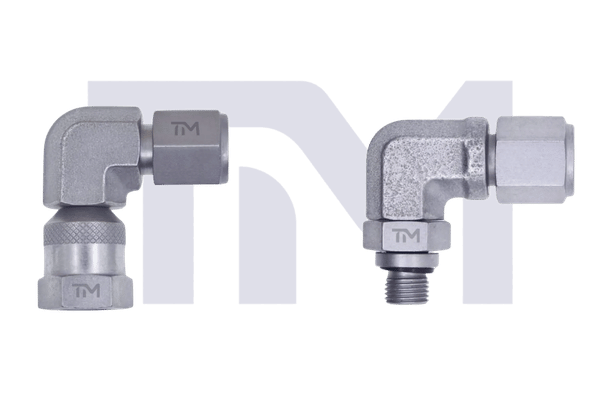
45° / 90°
Fixed-angle routing choices
100% inspection
Production inspection coverage
3-year
Quality warranty
Drawing-led
Two-interface verification
At a glance
Summary: Angled Pressure Gauge Connectors at a Glance
Selection risk: A wrong angle can clear one obstacle while moving the dial or tool path into another. Confirm the connection series and sealing geometry first, then pressure and operating duty, and only then use the angle to solve layout and viewing constraints.
10
Working days
We ship prototype parts in 10 working days after drawing approval.
100
Piece MOQ
We accept 100 pieces for standard configurations.
2
Sample dispatch
We provide a free sample shipped in 2 days.
3
Warranty years
We provide a 3-year quality warranty for supplied connectors.
Geometry screening
Fixed-Angle Routing for Hydraulic Diagnostics
A straight adapter can place the gauge body against a cover, hose, tube, or adjacent valve. An angled hydraulic gauge adapter changes the approach direction and the gauge plane, but its nominal angle alone does not establish clocking, wrench access, or interface fit.
Gauge-Plane Clearance Worksheet
Use five installation inputs to organize a 45° review, 90° review, or drawing review. The worksheet screens geometry; it does not issue a part number or pressure approval.
Open the clearance worksheet →- Gauge diameterBody envelope, not dial size alone
- Port axisDirection and mounting face
- ObstructionDistance and location
- Viewing directionRequired dial orientation
- Service clearanceTool and hand access
45° and 90° hydraulic gauge connector options
Both angles can move the gauge face away from a crowded port, yet they solve different routing shapes. Compare the installed envelope rather than choosing the smaller or larger angle by habit.
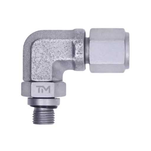
45° route
Partial directional change
45° route
A 45° pressure gauge connector suits layouts where a diagonal offset can clear the obstruction while keeping the gauge closer to the original axis. Check the resulting dial plane and wrench path because the shallower turn can still direct the body toward nearby hardware.
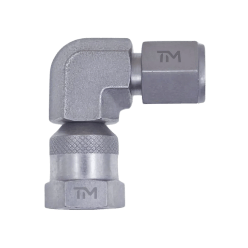
90° route
Right-angle directional change
90° route
A 90 degree elbow pressure gauge connector moves the gauge axis perpendicular to the port axis. Before you install a 90 degree elbow fitting, check the body envelope and fixed clocking against the released drawing.
Drawing review
Escalation route
Choose drawing review when the obstruction is irregular, the port orientation varies between machines, or the gauge must face a controlled direction. TIME can compare the routing sketch with the offered connector geometry before the configuration is released.
Angle-to-Port Orientation Schedule
| Selection factor | 45° review | 90° review | Escalate to drawing review |
|---|---|---|---|
| Routing change | Diagonal offset from the port axis | Full right-angle turn | Obstruction position is not dimensioned |
| Gauge-face plane | Calculate from the actual port axis | Calculate from the actual port axis | Viewing direction is mandatory or uncertain |
| Clearance envelope | Check gauge body, connector body, and tool path | Check gauge body, connector body, and tool path | Any diameter, offset, or service dimension is missing |
| Clocking | Do not infer it from the nominal angle | Do not infer it from the nominal angle | Fixed or rotatable state is not defined |
| Interface fit | Verify system and gauge sides independently | Verify system and gauge sides independently | Thread, seat, seal, or engagement is unclear |
Selection result: the table produces a review route, not an approval. Pressure capability, material suitability, component qualification, and the complete diagnostic assembly still need their own evidence.
“We use the angle to solve a packaging problem only after the two interfaces and the application evidence are defined.”
— TIME Hydraulic Engineering Team
Application inputs
Materials, Coatings and Operating Conditions
Material words such as carbon steel or stainless steel are not substitutes for a released configuration. Fluid, temperature, corrosion exposure, seal compatibility, and the current available coating must be reviewed as one application set. The material and finish must stay bound to a defined coupling configuration and service scope.
Application Data to Bind to the Drawing
Base material
Specify the required material or ask TIME to document the offered grade.
Surface protection
State indoor, mobile, marine, washdown, or corrosive exposure.
Seal interface
Identify the seat, cone, bonded seal, O-ring, or other exact geometry.
Process fluid
Name the hydraulic fluid and flag any non-mineral or special chemistry.
Temperature range
Give minimum, normal, and maximum operating temperatures.
Cleanliness need
Define protective packaging and cleanliness evidence expected at receipt.
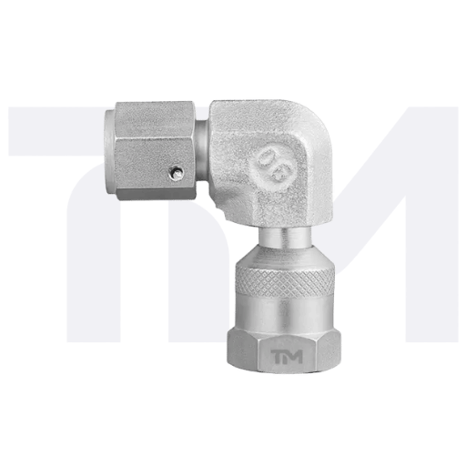
TIME capability
We manufacture a cone-seal design and bind the offered material, coating, and sealing form to the quotation or drawing. Send the mating-port standard or a clear dimensional drawing when the interface is uncertain.
Coating decision
Finish Evidence for the Actual Environment
A finish name is useful only when it is tied to the underlying material, preparation, thickness or acceptance method, and service environment. This page treats finish as a drawing-evidence question; ISO 15171-2 likewise defines its diagnostic-coupling scope through specified requirements and tests rather than a generic catalog label. The trade-off between appearance, storage protection, and service exposure belongs in the request.
Do not infer
One coating label does not define durability
The catch is that geometry, base material, edges, threads, handling, and the test method all affect the result. TIME records the selected finish on the commercial and drawing package when the order requires it.
01
Exposure
Record indoor, outdoor, salt, chemical, washdown, and abrasion exposure.
02
Concern
State whether appearance, storage protection, or service corrosion is the main concern.
03
Evidence
Ask for the offered finish and its applicable acceptance evidence on the quoted configuration.
Drawing evidence
Connection Interfaces, Dimensions and Pressure Evidence
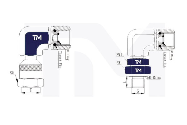
A connector specification for an elbow pressure gauge adapter must identify two interfaces separately. A male or female description, an NPT label, or a nominal thread size does not by itself define the seat, seal, tolerance class, or mating condition. ISO 15171-2 identifies dimensions, performance requirements, and test procedures for the hydraulic diagnostic couplings within its stated scope.
Angled Connector Drawing Evidence Pack
-
1. System side
Port standard, size, sex, seat, seal, engagement, and mating-part drawing.
-
2. Body and angle
45° or 90°, fixed or rotatable state, clocking, wrench flats, and envelope.
-
3. Gauge side
Gauge connection, seal geometry, body diameter, mass, and required dial plane.
-
4. Operating duty
Working and transient pressure, cycles, fluid, temperature, vibration, and cleanliness.
-
5. Release evidence
Drawing revision, qualification scope, production inspection, marking, and packaging.
| Review line | Buyer input | TIME review output | Boundary |
|---|---|---|---|
| 1 — system port | Standard, size, sex, seat, and seal | Offered mating interface on drawing | Thread diameter alone is incomplete |
| 2 — gauge port | Gauge connection and sealing form | Second interface called out separately | Do not copy the system-side description |
| 3 — routing | 45° or 90° target and port axis | Fixed-angle body orientation | Nominal angle does not prove clocking |
| 4 — envelope | Gauge diameter, obstruction, and service space | Dimensional clearance review | Drawing clearance is not pressure qualification |
| 5 — pressure states | Working, transient, and connection-state requirements | Configuration-specific evidence request | One maximum value cannot cover every state |
| 6 — dynamic duty | Impulse, cycle, vibration, and temperature profile | Applicable qualification scope | Static dimensions do not prove fatigue life |
| 7 — media | Fluid type and compatibility restrictions | Material and seal review | Special fluids require explicit agreement |
| 8 — surface | Corrosion environment and finish requirement | Quoted coating or surface condition | Generic resistance claims are insufficient |
| 9 — inspection | Critical characteristics and records required | Production inspection scope | Lot inspection differs from qualification |
| 10 — release | Revision, marking, packaging, and quantity | Comparable drawing and quotation package | Only the accepted revision controls supply |
Commercial handoff
Quote Inputs, Samples and Order Terms
| Commercial item | TIME commitment |
|---|---|
| Prototype | We ship prototype parts in 10 working days after drawing approval. |
| Small batch | We ship small-batch orders in 25 calendar days after drawing approval. |
| Production | We schedule production runs at 40 calendar days, confirmed with the quotation. |
| Minimum order | We accept 100 pieces for standard configurations. |
| Sample | We provide a free sample shipped in 2 days. |
| Payment | We use a 30% deposit with the balance before shipment, by T/T. |
| Delivery basis | We ship EXW, FOB and CIF. |
Inputs for a comparable quote
Price depends on the two interfaces, angle, material and finish, evidence scope, quantity, packaging, and delivery term. A clear data pack reduces clarification cycles and keeps alternatives comparable.
We handle submitted information as confidential.
Request a Connector Quote
System port and gauge connection drawings
45° or 90° routing sketch with obstruction dimensions
Pressure, duty, fluid, temperature, and environment
Quantity, sample need, inspection records, and Incoterm
SYSTEM / SPECIFICATIONS
Inspection, Documentation and Warranty
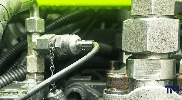
We complete 100% inspection and provide a 3-year quality warranty. The quotation or accepted quality document should identify which characteristics are checked, the applicable drawing revision, record format, sampling or full-inspection scope, and acceptance criteria.
01 ·
Dimensional conformity
Critical connections, sealing geometry, angle, and envelope dimensions are checked against the released definition.
02 ·
Qualification evidence
Pressure test evidence must match the relevant design family, material, interface, and test scope; a drawing alone cannot replace it.
03 ·
Production records
Required inspection records, marking, cleanliness, and packaging evidence are specified before order release.
Evidence separation: design qualification, production inspection, and complete-system approval answer different questions. Ask for each one that your project or supplier-quality plan requires.
Review workflow
How We Work: From Connection Data to Approved Drawing
1
Define
Send both interfaces and the application duty.
2
Screen
Compare 45°, 90°, and drawing-review routes.
3
Clarify
Close gaps in seals, geometry, materials, and evidence.
4
Quote
Fix quantity, sample, lead time, and delivery terms.
5
Approve
Accept the controlling drawing and quality scope.
6
Release
Inspect, mark, pack, and ship to the agreed record set.
Focused manufacturer
Parts We Manufacture: TIME Hydraulic Focus
IKIN® / TIME Hydraulic
IKIN is our registered trademark, and TIME Hydraulic is the operating company.
Manufacturing scope
We operate a 5,000 square metres production facility in China and are developing new workshops. Our product work centers on hydraulic diagnostic connections, test points, and hoses, so connector drawing review, inspection, and order handoff stay inside the same specialist manufacturing scope.
- Real first-party 45° and 90° pressure gauge connector product photography
- Full-range model review against the current TIME drawing
- Drawing-controlled inspection and a direct technical inquiry path
Hydraulic test points and hoses—nothing else.
Product-family continuity
The new timehydra.com page carries forward the first-party 45° and 90° product scope and real product media from the legacy site. Current quotations and drawings remain the control for configurations supplied after the migration.
Specialist review path
Hydraulic diagnostic products are our manufacturing focus, so the inquiry can move from two-interface identification to angle, envelope, evidence, sample, and order review in one technical handoff.
Buyer-owned inputs
Your machine port, gauge connection, operating duty, and installation envelope determine what must be checked. TIME records the offered answer in the drawing and quotation instead of asking a broad catalog label to carry the decision.
Engineering limits
Engineering Review Boundaries for Angled Connectors
An angled gauge connector should not be released from a product photo, nominal angle, or thread label alone. The wrong choice can shift the interference rather than remove it. Angle is not a substitute for connection, seal, pressure-duty, and material review.
01
Thread or seal identity is uncertain
Provide the mating-port standard, dimensions, seat detail, and seal geometry; the angle cannot correct an interface mismatch.
02
Clocking or gauge plane is critical
Show the port axis, viewing direction, obstruction, and fixed or rotatable requirement on the installation sketch. Fixed-angle and rotatable products are not interchangeable.
03
Pressure duty is not fully defined
Separate working, transient, connection-state, impulse, and complete-chain limits before selecting a configuration.
04
Fluid or temperature differs from the baseline
Identify the medium and operating range so material and sealing compatibility can be reviewed explicitly.
05
Qualification is being inferred from dimensions
Request applicable test scope and production inspection evidence as separate deliverables.
06
Maintenance work can expose stored energy
Follow the employer-authorized energy-control procedure and account for residual energy and possible reaccumulation before servicing.
Engineering Resources
45° & 90° Pressure Gauge Connectors Tools
Angle-to-Port Orientation Schedule
Evaluate the geometric routing constraints before committing to a 45° or 90° fitting. Determine whether the angle truly clears the obstruction.
Run scheduleAngled Connector Drawing Evidence Pack
Consolidate your working conditions, seals, and interface definitions into a single, clarified documentation package for quotation.
Build packageGauge-Plane Clearance Worksheet
Screen installation inputs including gauge diameter, tool access, and viewing direction to confirm the correct clocking and orientation.
Open worksheetRequest a Drawing for Your Angled Gauge Connector
TIME Hydraulic will review the 45° or 90° route against the interface, sealing, working-condition, and evidence inputs you provide. You receive a clearer basis for the drawing and quotation without turning a geometry worksheet into an engineering release.
System port
Gauge connection
Routing sketch
Working conditions
Quantity
Buyer questions
FAQ: Pressure Gauge Connector Questions
What is the difference between a 45° and 90° pressure gauge connector?
A 45 degree pressure gauge connector redirects the gauge axis by a shallower angle, while a 90 degree pressure gauge connector creates a right-angle turn. Either option still needs a drawing review of the port axis, dial plane, obstruction envelope, clocking, and two sealing interfaces.
Which angle fits a tight hydraulic installation?
The answer depends on more than the shortest visible path. Record the gauge body diameter, system-port axis, obstruction distance, desired viewing direction, and tool clearance, then compare those inputs with the actual connector envelope.
- Use 45° when a partial redirect may clear the obstruction and preserve access.
- Use 90° when a full right-angle route is required.
- Use drawing review when clocking or any envelope dimension is unknown.
Are fixed-angle and swivel gauge adapters the same?
No. A fixed angled gauge connector has a defined body geometry, while a swivel or rotatable adapter has a different movement and locking concept; the words must not be treated as interchangeable.
What connection details are needed on both sides?
Identify the exact standard, nominal size, male or female form, thread or stud-end series, seat, seal, and mating-component detail for the system side and the gauge side. A photo or thread diameter can support identification, but the released drawing must carry the final definition.
Can the elbow angle correct a thread or seal mismatch?
No. The elbow changes routing only; it does not convert an incompatible thread, seat, seal, or engagement condition unless the actual connector drawing explicitly defines both matching interfaces.
What pressure evidence should be checked?
Check the configuration-specific working limit, transient or impulse duty, temperature range, connection-state restrictions, and the lowest rating in the full gauge-and-hose diagnostic chain. Record every figure with its unit, such as bar or psi, and compare each connector, hose, and instrument included in the diagnostic kit.
Which material and coating should be specified?
Start with fluid compatibility, temperature, corrosion exposure, mechanical environment, and the project’s evidence requirement. TIME then documents the material, sealing form, and offered surface condition for the quoted configuration.
What should I send for a drawing and quotation?
Send drawings or clear details for both connections, a routing sketch, gauge envelope, pressure and duty profile, fluid, temperature, material or coating needs, quantity, inspection records, packaging, and delivery term. Note any fixed clocking, marking, confidentiality, or sample-approval requirement.
What are the sample, MOQ, lead-time and warranty terms?
We provide a free sample shipped in 2 days, accept 100 pieces for standard configurations, ship prototypes in 10 working days, schedule small batches at 25 calendar days, and production runs at 40 calendar days. We provide a 3-year quality warranty, with the order configuration and release terms recorded in the quotation.
Why can a pressure gauge connection leak even when the thread appears to fit?
A similar-looking thread can still have a different pitch, tolerance, seat, sealing location, or required engagement. Surface condition, contamination, damaged seals, misalignment, and an incorrect tightening method can also affect the joint, so the mating definition and approved procedure both matter.
