Hydraulic test points and hoses only

Hydraulic Test Fittings for Cranes

Bulk production in 10–30 working days EXW, FOB, CIF or CFR

Port-photo and drawing review

Process Requirements

  • Verify the crane’s actual diagnostic node, port geometry and sealing method before choosing a fitting.
  • Specify the test hose from steady pressure, transients, fluid, temperature and movement—not from reach alone.
  • Bind the pressure gauge, hose assembly and test point to one measurement objective and one written approval pack.

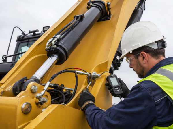
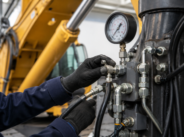
TIME Hydraulic reviews crane hydraulic test fittings as a measurement chain: machine port, diagnostic coupling, mobile crane test hose, gauge connection and proof documents. Send a port photo, OEM hydraulic drawing or existing part marking, and we will return a selection basis for the current TIME drawing.

A part number is confirmed only after the machine-side port and test-side connection are separated in the review.
Specifications

Product scope
Hydraulic test points and test hoses
Bulk production
10–30 working days
Standard fitting MOQ
100 pieces
Custom hose quantity
Set by assembly drawing and quotation
Payment
T/T 30% as deposit and T/T 70% before delivery
Trade terms
EXW, FOB, CIF and CFR

Crane Diagnostic Access Matrix

The matrix turns a partial request such as “M16 test point for a crane” into the inputs needed for a defensible selection. It does not replace the crane manufacturer’s hydraulic schematic, service procedure or authorization for the test condition.

ANALYZE NODE
Crane Diagnostic Authorized Node Test
STEP 01

Authorized diagnostic node

Identify the circuit function and OEM test location for boom, luffing, slew, winch, steering, outrigger or another hydraulic function. Record whether the procedure calls for a static reading, a controlled operating cycle or a comparison between points.

Crane Hydraulic Machine-Side Port Connection
STEP 02

Machine-side port

Capture the thread designation, pitch, port form, sealing surface, spotface and available installation envelope. A nominal thread can appear correct while the stud end, O-ring housing, cone or flare is wrong.

Test-Side Diagnostic Coupling for Cranes
STEP 03

Test-side interface

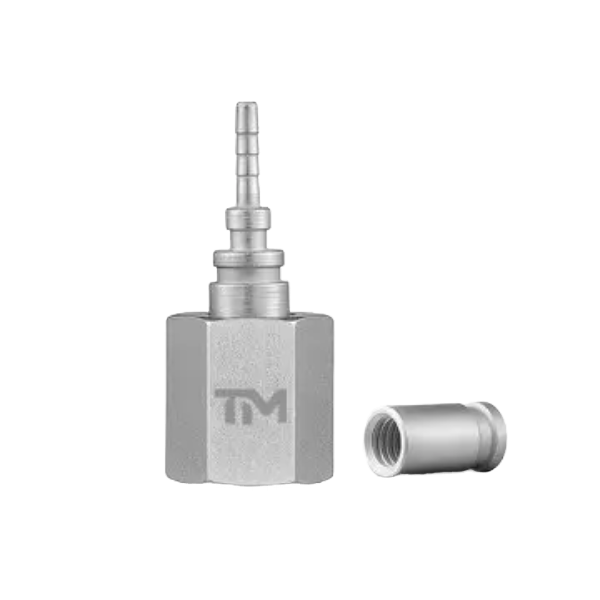
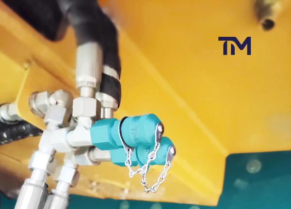
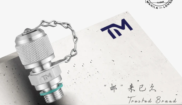
Separate the installed stud or adapter from the diagnostic coupling used by the hose. ISO 15171-2:2016 gives scope for an M16 × 2 diagnostic coupling, but the standard does not prove a TIME model rating or a crane fit.

Pressure Measurement Chain in Crane Hydraulics
STEP 04

Measurement chain

For selection support, review custom hydraulic test hose assemblies when the specified connection family matches the drawing and operating conditions.

State the expected steady and transient pressure, fluid, temperature, gauge range, accuracy target and calibration status. The hose route must also account for articulation, abrasion, heat, sharp edges and technician access.

Operating-state boundary

Follow the crane OEM procedure, isolate stored energy where instructed and keep personnel outside suspended-load and movement danger zones. Crane inspection and hydraulic service decisions belong to qualified personnel; a diagnostic fitting does not authorize the operating condition.

Materials, Seals and Operating Environment

Material choice begins with the fluid and exposure at the actual crane location. The trade-off is specific: corrosion resistance, fluid compatibility, temperature and cost must be balanced at the installed position rather than treated as one universal material rule.

Fluid boundary: The published scope of ISO 15171-2:2016 addresses mineral-oil systems and places other fluids under agreement between supplier and purchaser. That is why the actual fluid designation belongs in every selection review.

Materials, Seals and Operating Environment for Hydraulic Systems

Carbon steel body

Use the current drawing to confirm the steel grade, surface treatment and corrosion expectation for protected or general industrial positions. Outdoor salt, washdown and chemical exposure may change the decision.

Stainless steel body

Specify the corrosion environment rather than asking only for “stainless.” The offered grade, mating material and sealing system must remain compatible with the fluid and port.

NBR sealing option

Provide the exact hydraulic fluid, additive package and minimum-to-maximum temperature band. Mineral-oil context alone is not enough when the crane uses a specialty or fire-resistant fluid.

FKM sealing option

Higher temperature resistance does not make an elastomer suitable for every medium. Selection still follows the named fluid, concentration, duty cycle and current seal data.

EPDM sealing option

EPDM requests require a fluid-specific review because common petroleum-based hydraulic oils can conflict with the material. Send the fluid manufacturer and product designation before the seal is fixed.

Protective cap & cleanliness

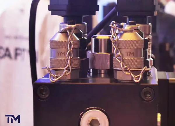
The cap, tether and storage practice protect the diagnostic interface between tests. Include the required cleanliness and contamination-control method in the maintenance procedure.

Environment data to send

  • Fluid name
  • Minimum temperature
  • Maximum temperature
  • Outdoor exposure
  • Salt or chemical contact
  • Vibration
  • Washdown
  • Storage interval

Connection Architecture for Crane Test Points

Crane test-point requests often combine the machine port, its installed adapter and the hose coupling in one description. The review identifies each interface separately so an adapter cannot conceal an unverified port match.

Connection Architecture for Crane Test Points
Interface family to identify Evidence to send Mismatch prevented
M16 × 2 (M16x2) diagnostic coupling or test nipple Existing coupling photo, mating-hose end and current drawing Confusing the diagnostic side with the machine stud end
Metric O-ring port Thread, pitch, housing geometry, O-ring position and spotface Matching pitch while missing the sealing architecture
BSPP port G thread, seal form and port-seat detail Assuming every parallel pipe thread seals the same way
NPT or NPTF port Taper designation, engagement condition and OEM procedure Substituting a parallel-thread adapter into a tapered port
JIC 37-degree flare Tube or hose-end size, male/female side and flare condition Treating thread engagement as proof of flare contact
ORFS face seal Face geometry, O-ring size, tube end and clearance Missing face damage or the wrong O-ring arrangement
DKO 24-degree cone Cone type, tube series, swivel end and model drawing Mixing a 24-degree cone with another metric connection
Gauge connector, adapter, tee or bulkhead Installation envelope, load path, orientation and hose route Creating a side load, collision point or inaccessible gauge

Thread-only selection is the trap because it creates a sealing risk even when the pitch appears to match. A matching pitch does nothing for sealing when the port housing or seat is wrong. A qualified review provides the standard fix: confirm against the OEM geometry, the current TIME drawing and the relevant ISO 1179 or ISO 6149 port family.

ISO 1179 and ISO 6149 port families pair nominal threads with defined port housings, stud ends and seals. That is why TIME asks for the drawing or geometry around the thread rather than selecting from “BSP,” “metric” or “SAE” alone.

Selection Data and Evidence Requirements

ISO 9110-1:2020 provides measurement-principles context for hydraulic fluid power. Replace the table’s example formats with values from the crane manual, the installed component and the intended measurement method.

Selection Data Evidence 02
Selection Data Evidence 01
Selection field
Required order input
  • Crane and circuit identity
    1 equipment class, model/serial context and 1 named hydraulic function
  • Port evidence
    2 clear views plus 1 dimensioned OEM or service drawing where available
  • Thread and seal
    4 fields: diameter × pitch, male/female side, seal form and port depth in mm
  • Pressure duty
    3 values where available: normal, permitted peak and transient/impulse condition, stated consistently in bar, MPa or psi
  • Temperature duty
    2 endpoints: minimum and maximum fluid/ambient temperatures in °C or °F
  • Hose route
    4 inputs: required length in mm, bend points, motion envelope and protected clamp locations
  • Measurement objective
    4 inputs: expected pressure band, gauge range, accuracy class and calibration date
  • Proof package
    4 items: current drawing revision, material/seal declaration, inspection scope and warranty wording

Interactive selection tools

  • Crane Diagnostic Access Matrix

    For selection support, review angled pressure gauge connector options when the specified connection family matches the drawing and operating conditions.

    Organize the OEM node, machine port, test-side connection and measurement objective before requesting a part number.

  • Pressure Evidence Checker

    Separate working, proof, burst and impulse evidence and flag the fields that still need a current assembly record.

  • Mobile Crane Test Hose Route Planner

    Review length, movement, bend, abrasion, heat and technician access without creating an operating instruction.

  • Crane Fitting RFQ Input Checker

    Build a clean enquiry pack with port evidence, fluid, pressure, hose and document requirements.

Pricing, Lead Time and Order Terms

Price follows the fitting or hose assembly, connection geometry, body and seal material, pressure evidence, quantity, hose length, end configuration and document scope. TIME returns the exact figure in a written quotation tied to the selected drawing.

Pricing and Order Terms for Hydraulic Fittings

Cost drivers in a crane diagnostic assembly

Driver Effect on the quotation Input that controls it
Machine-side connection Stud geometry and sealing method set the adapter route Port drawing, dimensions and seal form
Body and seal material Corrosion, fluid and temperature requirements change materials Named fluid and exposure band
Hose assembly Length, ends, protection and pressure evidence set assembly scope Route sketch and duty values
Quantity and model mix Setup and inspection are distributed across the order Quantity per part number and reorder plan
Documentation Drawing, traceability and test-report scope change the release pack Written acceptance checklist
Commercial Terms and Lead-Time Start Point

Commercial terms

  • Bulk production runs 10–30 working days after the order inputs and drawing are confirmed.
  • The standard catalogue fitting minimum order is 100 pieces; custom hose assemblies are quoted to the requested configuration and quantity.
  • Payment is T/T 30% as deposit and T/T 70% before delivery.
  • TIME quotes EXW, FOB, CIF and CFR trade terms.

Lead-time start point

The production clock starts after the selected drawing, quantity, commercial term and acceptance scope are confirmed. A port question or a late hose-end change returns the order to drawing review because it changes the item being released.

SPECIFICATION // TRACEABILITY

Inspection, Traceability and Approval Pack

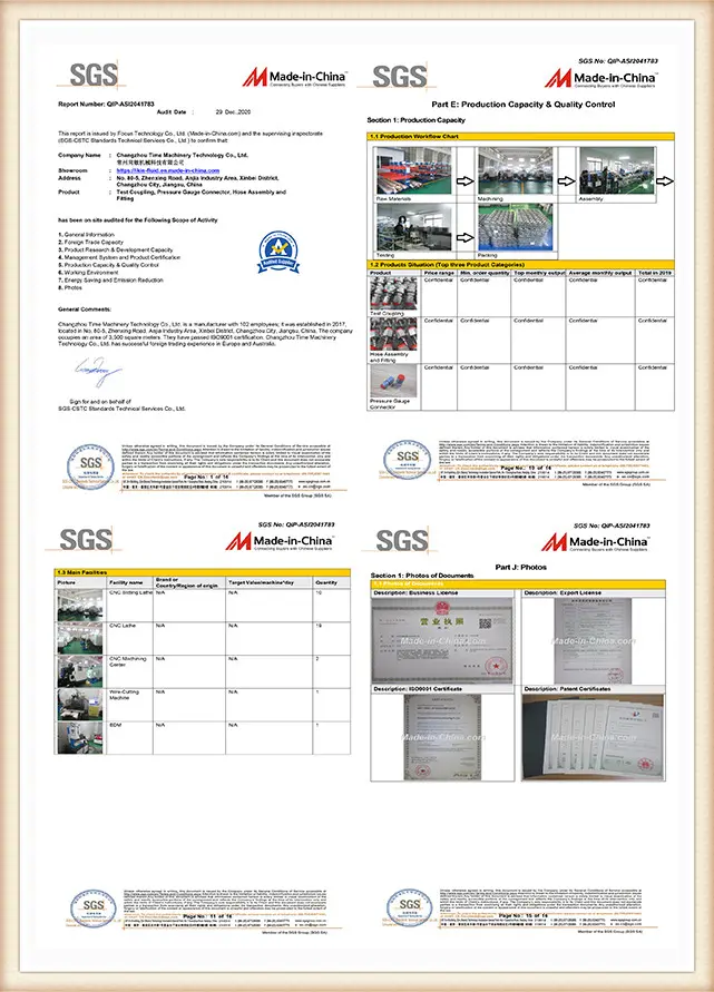
Quality review must connect a physical item to the drawing and requirement that govern it. A standard name, certificate logo or catalogue statement is not a substitute for the selected model’s inspection and test record.

Define the Approval Pack →
Inspection Traceability and Approval Pack
  • We manufacture only hydraulic test points and test hoses.
  • Our range covers cone-seal, zero-leakage designs.
  • We carry out 100% inspection before release.
  • We provide a 3-year quality warranty.
  • We supply a full range of models.
  • We operate a 5,000 m² production facility, with new workshops under development.
Drawing identity
Part number, revision, dimensions, machine-side connection and test-side interface.
Material identity
Body material, surface treatment, seal material and declared fluid/temperature basis.
Inspection and test scope
Characteristics checked, sampling or 100% scope where agreed, acceptance criteria and report format.
Commercial remedy
Written warranty period, exclusions, traceability expectation and response if the supplied item misses the agreed criteria.

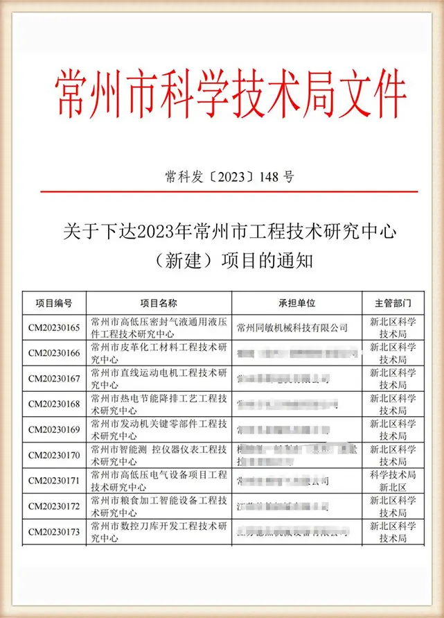
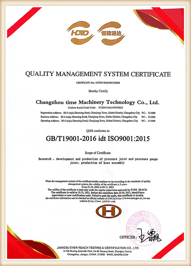
Management-system certificate

Confirm the issuing body, certificate number, scope and validity for the operating company. A management-system certificate describes the certified system; it is not a pressure rating for a fitting.

Product and assembly record

Match the report to the offered part number, drawing revision and acceptance method. ISO 6605:2017 supplies test-method context for hydraulic hoses and hose assemblies, not automatic compliance for an unlinked product.

Evidence objects to request

  • Current fitting or hose-assembly drawing
  • Material, coating and elastomer declaration
  • Inspection plan and released inspection record
  • Working pressure, pressure-test and impulse-test records where required by the application
  • Lot or batch traceability fields
  • Written warranty scope and remedy
Traceability Evidence Objects

Impulse duty changes the evidence question

ISO 6803:2017 covers impulse testing for hydraulic hose assemblies exposed to pulsating service. Ask whether the offered assembly has an applicable record; do not convert the standard’s test categories into the crane’s operating limit.

How We Work: TIME Selection Review

STEP 01

Send the crane context

— share the model, circuit function, OEM hydraulic schematic or service instruction and intended diagnostic condition.

STEP 02

Identify the machine port

— provide photos, dimensions, thread/pitch and sealing geometry from the installed connection.

STEP 03

Define the measurement

— state normal and peak pressure, transient duty, fluid, temperature, gauge range and calibration status.

STEP 04

Route the test hose

— mark length, bends, articulation, abrasion, heat, clamp points and the technician’s gauge position.

STEP 05

Review the current drawing

— TIME maps the inputs to a current fitting and hose drawing and resolves open interface questions before release.

STEP 06

Fix the order pack

— the quotation records quantity, production term, payment, trade term, inspection scope, traceability and warranty wording.

Drawing notes that prevent rework

Drawing note What to state Why it matters
Port and seal Thread, pitch, housing, cone/flare/face and elastomer Stops a thread-only substitution
Pressure basis Normal, peak and transient/impulse condition Separates operating duty from catalogue shorthand
Hose route Finished length, moving points, bend and protection Prevents pull, rubbing and inaccessible gauge placement
Measurement basis Gauge range, accuracy class, calibration and reading objective Keeps the reading useful, not merely contained
Acceptance pack Drawing revision, report, traceability and warranty scope Gives procurement one release basis

Limits of a Crane
Test-Fitting Selection

A test point and hose make measurement access possible; they do not determine the crane repair, prove the circuit is safe to energize or correct a poor measurement plan. Treating access hardware as the diagnosis is the wrong choice; the component decision stays inside the OEM procedure.

Stored-energy boundary

HSENI guidance for vehicle hydraulic systems reinforces stored-energy and maintenance controls. The crane manufacturer’s service procedure and qualified personnel still govern the diagnostic condition.

Situation
Why the fitting is not the answer
Next action
The diagnostic node is unknown
A convenient port may not represent the pressure needed for the fault check
Use the OEM schematic and service procedure to identify the node
The thread is known but the seal is not
Thread engagement can occur without the correct sealing contact
Measure the port housing and send a section drawing or clear close-ups
The hose crosses a moving or hot zone
Reach alone does not control abrasion, pull, bend or heat exposure
Change the gauge position, route or protected length before selecting the assembly
The pressure is highly pulsating
A static rating does not establish impulse performance
Request an applicable assembly record and review the measurement dynamics
The gauge range is poorly matched
The connection may hold pressure while the reading lacks useful resolution
Select the measuring device from the expected band and accuracy objective

Hydraulic Test Fitting Engineering Tools

Determine the optimal placement for test points across mobile crane hydraulic circuits. Map access points for diagnostic efficiency.

Validate system pressure ratings and ensure compliance with ISO safety parameters. Generate standardized diagnostic reports.

Calculate exact hose lengths and routing configurations to avoid abrasion and pressure drops during field testing.

Verify RFQ parameters and operational variables before initiating custom test fitting and hose assembly production.

Crane Hydraulic Test Fitting FAQs

Start with the OEM diagnostic node, then identify the machine-side port and seal from a drawing or measured geometry. Crane brand and nominal thread alone do not establish a match; TIME confirms a part number against the current drawing.