
Get in touch with TIME Company

Pressure Gauge Connector Products & Selection
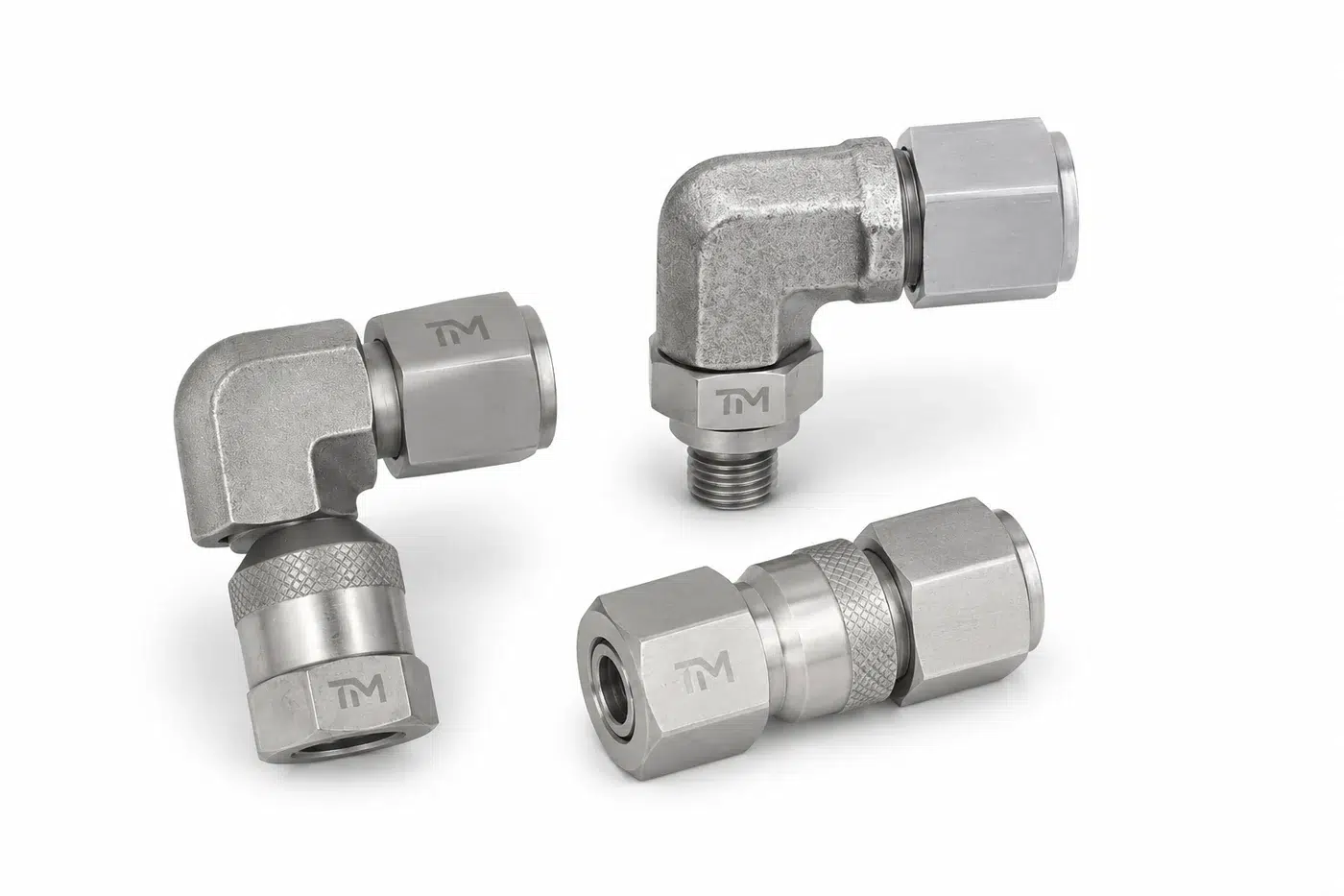
For hydraulic pressure-testing layouts, TIME provides pressure gauge connectors and adapters. Before quoting, we examine the gauge-side and system-side interfaces, sealing method, body angle, mounting path and operating conditions.
- Engineer-reviewed drawings
- Straight, angled, DKO and bulkhead routes
- Traceable selection inputs
- Global B2B supply
Submission Protocol
Send a part number, drawing, or a clear photograph with a ruler beside it. Drawings and specifications are treated as confidential and protected.
Selection at a Glance
The wrong choice is rarely visible from the outside: two connectors can share a visible thread while the sealing seat, body angle or mounting geometry differs. A short drawing review costs less than a leak investigation after installation.
Start Trial Order
SEC.01
Connector families
45° and 90° angled, bulkhead, straight and DKO routes
SEC.02
Seal review
Thread, cone, bonded seal or O-ring interface
SEC.03
Evidence pack
Drawing review, inspection scope and requested certificates
SEC.04
Quote response
Within one business day, reviewed by an engineer
SEC.05
Prototype timing
3 working days after drawing approval
SEC.06
Trial order
Starts from 100 pieces with your logo included
Pressure Gauge Connector Families
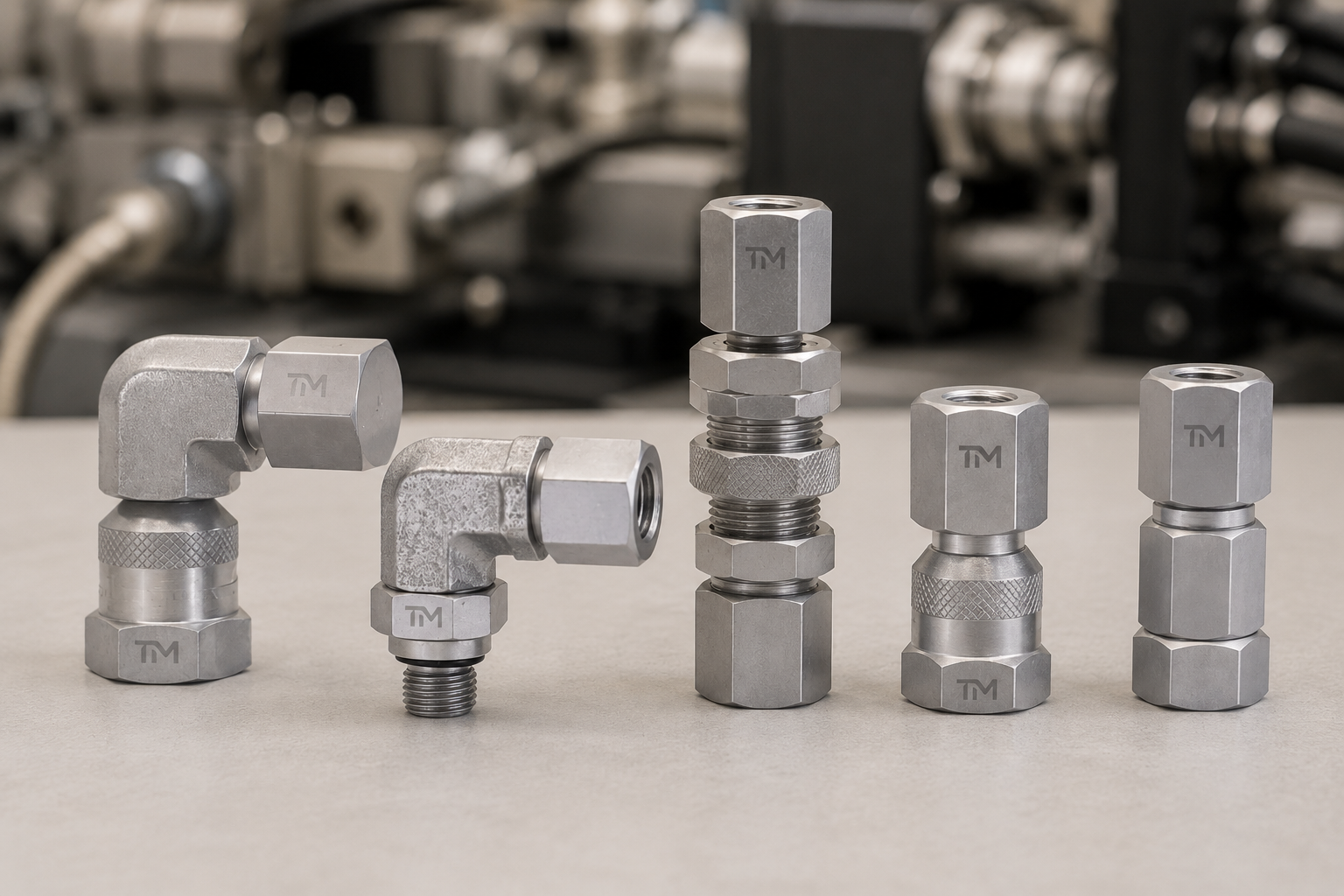
TIME builds the selection around body geometry, mounting location and the two mating interfaces rather than a generic fitting label. Available space, gauge orientation and the machine-side connection determine which of the three connector families is the correct starting point.
Evidence carried into the review: Interface decisions are checked against the applicable drawing and the connection principles in ISO 15171-2 and ISO 8434-1 where relevant. This reduces mismatch risk because TIME engineers record the requested evidence and apply 100% inspection to the agreed order scope.
Engineering selection rule
Thread fit alone is not proof of a safe connection. Check the interface, seal, pressure profile, test medium, cleanliness requirement and the lowest-rated component in the assembly.
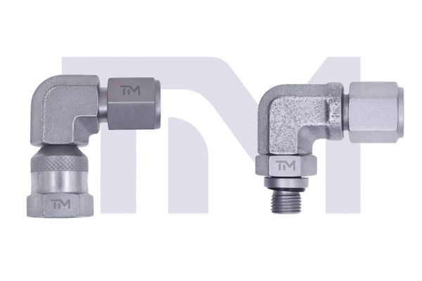
45° & 90° Pressure Gauge Connectors
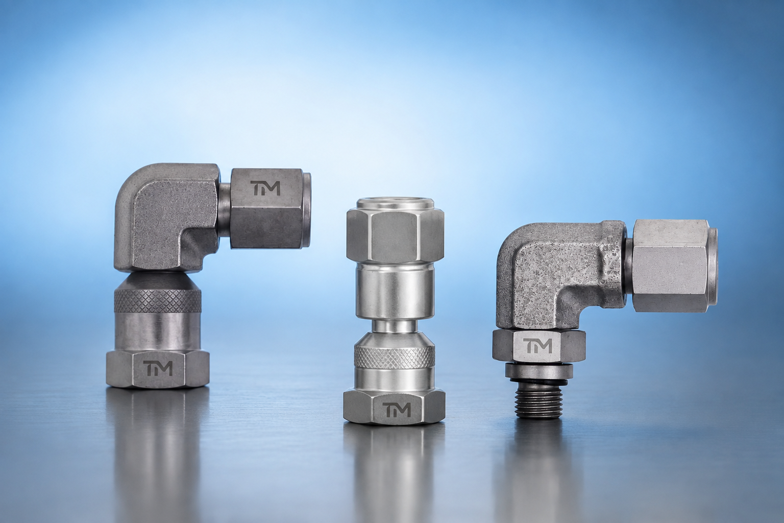
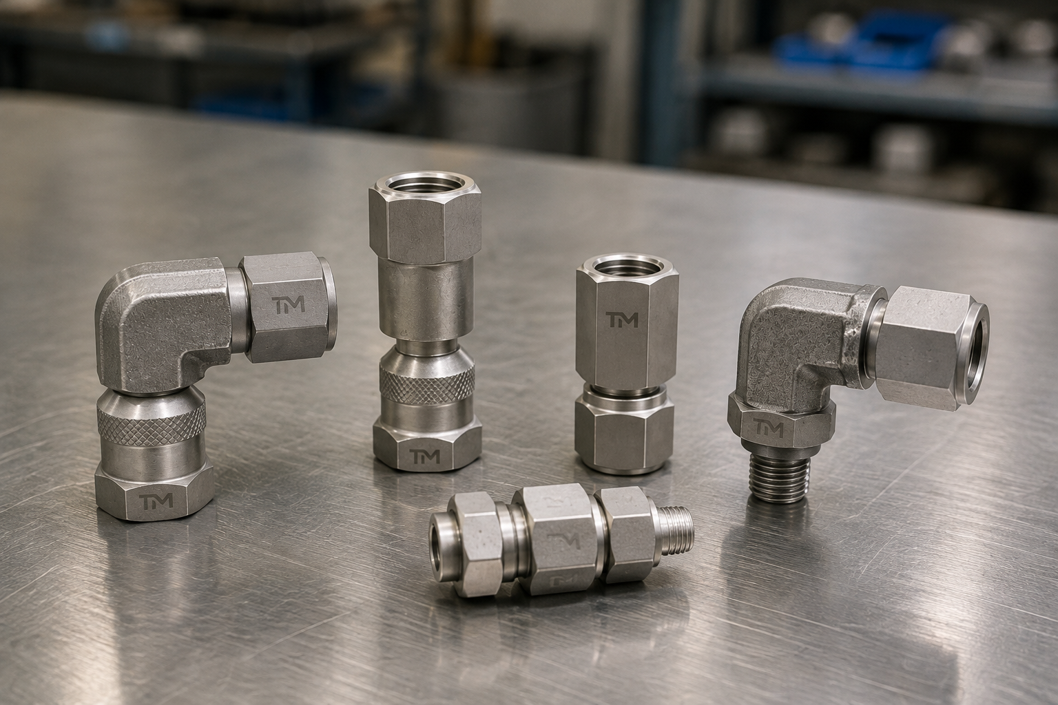
Use an angled body when the gauge or downstream connection must turn around a guard, tube, valve block or other obstruction. State the required angle, outlet direction, gauge envelope and wrench clearance on the drawing.
View Specifications →
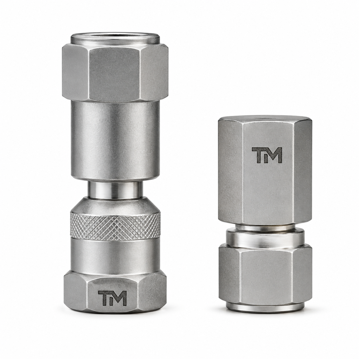
Bulkhead Pressure Gauge Connectors
Use a bulkhead route when the gauge connection must pass through a panel or mounting surface. Confirm panel thickness, hole geometry, mounting side and service access before approval.
View Specifications →
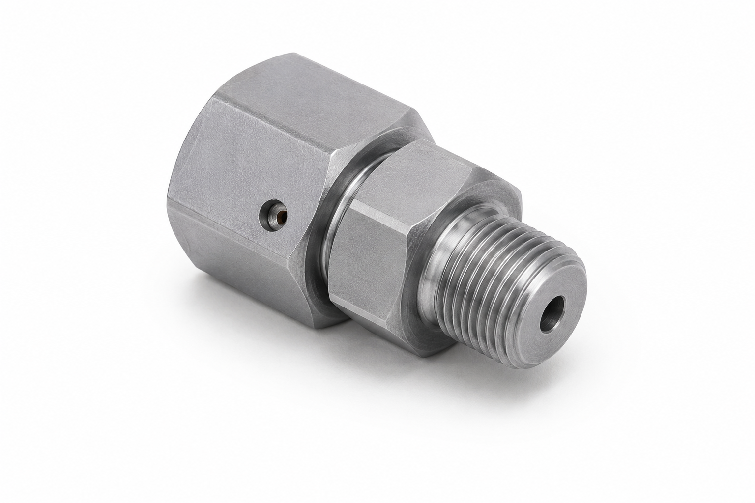
Straight & DKO Pressure Gauge Adapters
Use a straight route for an in-line connection, or define a DKO adapter where the machine side uses the corresponding 24-degree cone geometry. Confirm both connection ends, tube outside diameter or series where applicable, seal form and available clearance.
View Specifications →
Materials and Seal Interfaces
Material choice follows the hydraulic medium, environment, corrosion exposure and the inspection requirements in your drawing. TIME confirms the exact material and seal combination against the approved part definition.
Design inputs for a complete connector
State whether each end is male or female, then identify the gauge-side and machine-side interfaces, nominal size, body geometry and any high-pressure service condition. Include the pump, valve block or other machine port that the connector must connect to so the review covers both ends.
Selection input
Base material
Steel, stainless steel or drawing-defined grade
Corrosion, strength and lifecycle conditions differ
Thread form
Metric, BSP, NPT, SAE, JIC or other defined interface
Thread standards are not interchangeable by appearance
Seal method
Cone, O-ring, bonded seal, gasket or taper sealant
Seal method controls seating and leak risk
Hydraulic medium
Oil, water-glycol or another specified fluid
Elastomer and cleanliness requirements must match service
Body Geometry
Record whether the connector must remain straight or turn through 45° or 90°, together with the installed envelope and outlet direction. Angle choice is an access decision, not a substitute for defining both mating interfaces.
Mounting Geometry
For a bulkhead connector, include panel thickness, mounting-hole details, the retained side and the accessible service side. These inputs keep the mounting decision separate from thread and seal identification.
Sealing and Installation Control
The correct seal is part of the connector specification, not an installation afterthought. Tapered threads and parallel or straight interfaces use different sealing mechanisms, so the drawing must name the thread and seal together.
Buyer advisory
- Measure thread type, diameter and pitch before ordering, including any DIN interface requirement.
- Do not apply thread sealant to a face-sealing or O-ring interface unless the approved instruction requires it.
- Confirm depressurization, isolation and leak-check procedures before connection or removal.
Angle and Clocking Confirmation
For a 45° or 90° connector, show the outlet direction, gauge envelope, wrench swing and nearby obstructions. The body must clear both installation and later service movement.
Drawing-led Confirmation
TIME records the interface, body geometry, material, seal and inspection request in the quotation so the approved part is clear to production and receiving. This helps ensure the selected connector matches the approved route.
Pricing, Lead Time and Order Terms
Pricing follows the approved interface, material, seal, geometry, quantity and inspection scope rather than a generic connector label. Send the part number or drawing and TIME returns a written quotation within one business day.
What moves the quotation
- Gauge-side and system-side thread standards
- Straight, angled, DKO or bulkhead geometry
- Material, seal and finish requirements
- Quantity, packaging and inspection documents
Bronze ROI proof
Value is expressed as fewer avoidable selection loops, clearer drawing review and a controlled first order. No unsupported savings percentage or payback period is claimed.
Procurement path
Samples are available and normally dispatched in 3 working days; whether a sample is chargeable depends on the item. Production runs are scheduled at 10–30 working days and confirmed in the quotation.
Quality and Evidence Pack
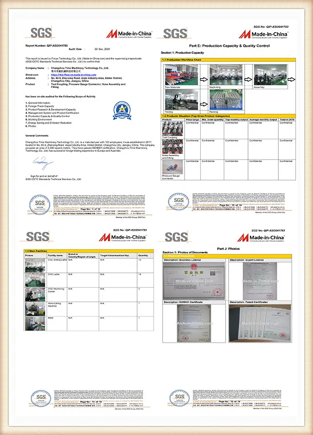
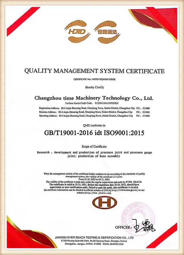
This page organizes the three pressure gauge connector families for drawing and interface review. For each agreed order, TIME applies 100% inspection and provides a 3-year quality warranty; the quotation records the applicable inspection and warranty scope.
Inspection workflow
- Review drawing, interface, body geometry and seal definition.
- Confirm material and process instructions.
- Inspect the finished parts against the approved definition.
- Release the requested inspection documents.
Supplier evidence
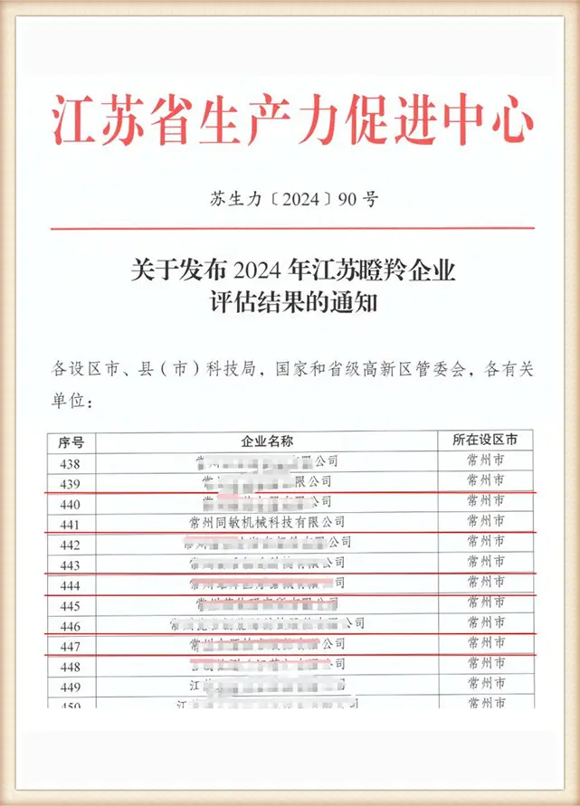
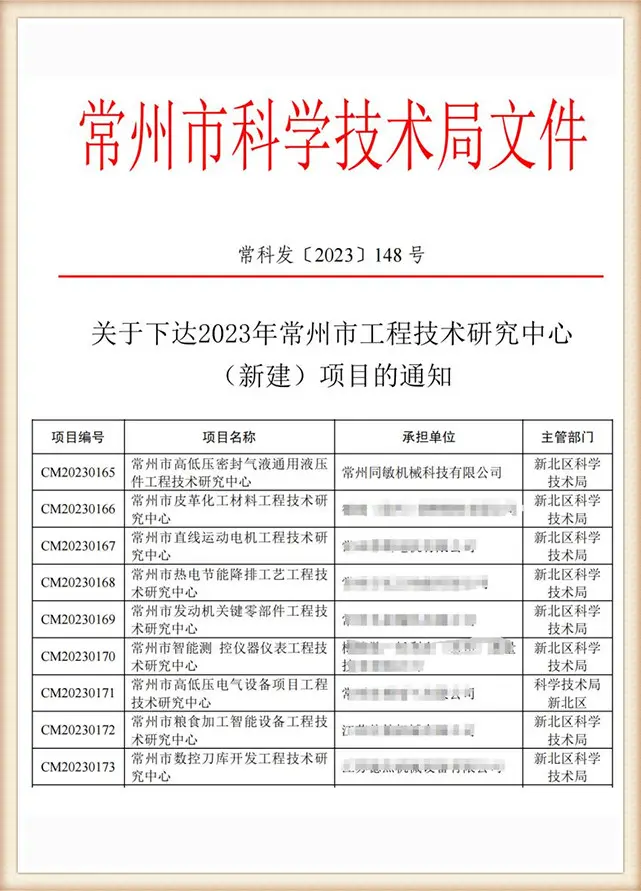
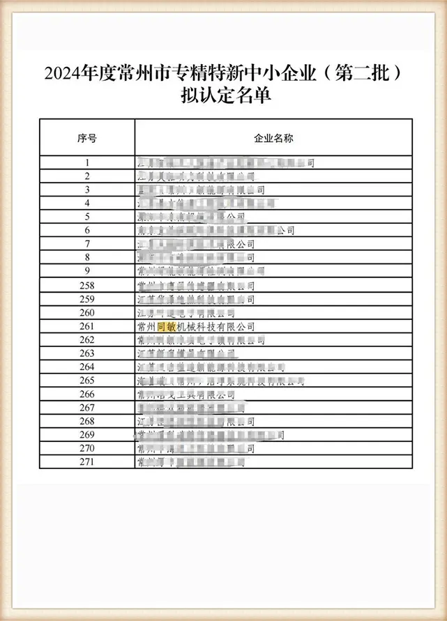
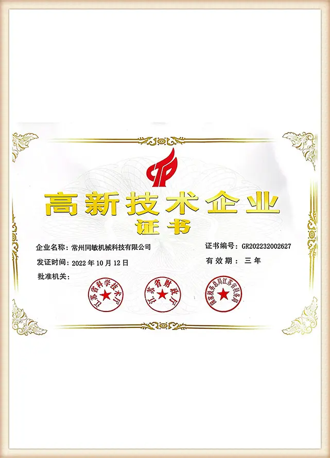
State the certificates, drawings and inspection records your approval process needs. TIME confirms availability, validity and scope in the quotation instead of treating a logo or generic certificate as product approval.
“The lowest-rated component governs the assembly, so selection starts with the complete interface and operating state.”— Selection note
TIME Connector Enquiry Workflow
When the interface is uncertain, the wrong call creates a rework loop; TIME makes the review output visible before production starts under ISO 8434-1 connection principles. The trade-off is simple: spend a few minutes confirming the route now, or spend more time correcting an installed mismatch.
01 Send inputs
Share a part number, drawing or clear photograph with a ruler.
02 Review interfaces
We map thread, seal, material, route and access conditions.
03 Receive quotation
The engineer-reviewed quote states scope, timing and requested evidence.
04 Approve prototype
Prototype parts ship in 3 working days after drawing approval.
05 Release production
Production runs are scheduled at 10–30 working days.
06 Receive evidence
Inspection and certificate documents follow the agreed order scope.
FIG. 01 / ADAPTER
Buyer situation
Starting route
First input to send
Gauge must sit at the port
Direct adapter
Both thread definitions and available clearance
Gauge needs remote access
Hose-connected test point
Hose path, end fittings and length
Permanent branch is required
Tee connection
Branch orientation and isolation arrangement
Engineering Tools
Pressure Gauge Connector Questions
How do I choose a pressure gauge female connector?
Provide the gauge thread, system-port thread, pitch, seal form, material, medium and available clearance. TIME checks both interfaces before quoting.
When should I choose a 45° or 90° pressure gauge connector?
Choose an angled body when a straight connector conflicts with a guard, tube, valve block, viewing direction or wrench envelope. Show the required angle and outlet direction on the drawing rather than selecting from appearance alone.
What information is needed for a bulkhead pressure gauge connector?
Send the panel thickness, mounting-hole geometry, installation side, service side and both mating interfaces. Include nearby obstructions so the connector and retaining hardware remain accessible.
What defines a straight or DKO pressure gauge adapter?
Define both connection ends, the seal form and the available in-line clearance. For a DKO end, also identify the applicable tube outside diameter or series and the mating cone geometry.
Are pressure gauge connector threads interchangeable?
No. Thread angle, pitch and sealing method must match; a connector that threads together can still leak or damage the port.
How fast can TIME provide a prototype?
Prototype parts ship in 3 working days after drawing approval. The quotation confirms the exact scope and schedule.
Can TIME support a trial order?
Trial orders start from 100 pieces with the buyer’s own logo included. Sample availability and any charge are confirmed per item.
Send Your Connector Details to TIME
Tell us the connection route, thread or part number, material, seal, medium and quantity. Within one business day, TIME returns an engineer-reviewed quotation and keeps drawings and specifications confidential.
Request a drawing reviewReferences & Sources
- HSE GS4 — Safety requirements for pressure testing
- HSE pressure-test specification — stored energy and rupture hazards
- ISO 15171-2 — Hydraulic fluid power connections for diagnostic measurement
- ISO 8434-1 — Metallic tube connections for fluid power and general use
- Thread and seal selection guide (generic technical reference)
