
Get in touch with TIME Company

Hydraulic Test Points for Excavators
TIME produces hydraulic test points and matching test hoses for planned pressure access to excavators and other mobile equipment. Provide machine, circuit and existing-port information, and our team will prepare an application-specific connection short-list and product drawing for comparison.
Request an Excavator Test-Point Drawing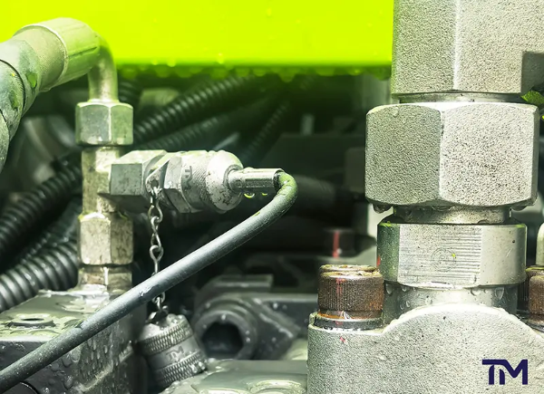
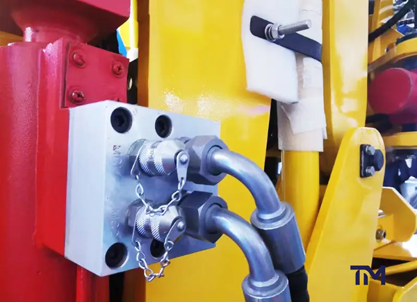
Manufacturing Standards
01
Focused production
Hydraulic test points and hoses only
02
Release control
Every product inspected before shipment
03
Commercial assurance
3-year quality warranty
Excavator Test-Point Specification Summary
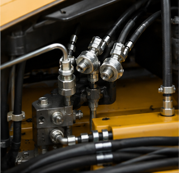
An excavator hydraulic test point is specified as part of a measurement chain, not solely by thread size. The ordered drawing defines the final connection, seal, material, pressure boundary and diagnostic-side interface.
-
ProductHydraulic pressure test point or diagnostic coupling
-
Scoped pressureUp to 63 MPa / 630 bar for a legacy bulkhead configuration
-
Connection formsBulkhead, DKO, ORFS, JIC, cutting ring, tee, tube and stud
-
MaterialsDIN 1.0718 carbon steel, 304 or 316L stainless steel
-
Finish optionsZinc or hexavalent-chromium-free zinc-nickel on applicable steel parts
-
Seal optionsNBR, FKM and EPDM within the confirmed configuration
-
Fluid baselineMineral-oil-based hydraulic fluid; other media require review
-
Supply termsSamples, production, inspection and warranty documented below
Scope note The lowest applicable limit in the machine port, test point, coupling, hose, gauge or procedure governs. A catalogue rating does nothing for a lower-rated hose or gauge, and a 630 bar working-pressure statement does not by itself authorize connection while the circuit is pressurized. The wrong answer is to treat one component rating as approval for the complete system.
The Excavator Pressure-Access Map
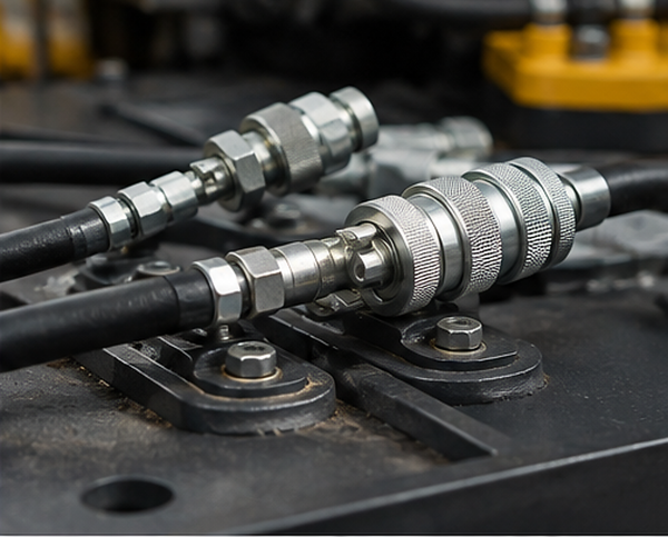
The appropriate mobile equipment test point begins with the approved diagnostic goal and circuit. TIME compares the machine procedure and existing access geometry to a connection family, test hose and measurement range.
| Diagnostic objective | Circuit category | Machine evidence to verify | Port information to record | TIME form to evaluate | Connection state | Diagnostic-side inputs | Release evidence |
|---|---|---|---|---|---|---|---|
| Confirm supply pressure | Main system or pump | Model-specific schematic and service procedure | Thread, seat, envelope and access direction | Bulkhead, stud or tube form | Depressurized unless an approved product limit and procedure say otherwise | Hose rating, gauge range and calibration status | Drawing, rating scope and inspection statement |
| Assess control response | Pilot or control | Named circuit and expected steady-state value | Existing plug or coupling geometry | DKO, cutting-ring or compact stud form | Verify before selection | Microbore hose, sensor end and measurement objective | Interface drawing and seal specification |
| Compare left/right function | Travel | Serial range and test condition from the manufacturer | Port type and available service envelope | Tee, tube or bulkhead form | Verify before connection | Two matched channels where the procedure requires comparison | Revision-controlled part list |
| Check function pressure | Swing | Service-manual reference and measurement point | Thread, seal face and orientation | ORFS, JIC or stud form | Do not infer from working pressure | Hose length, gauge end and safe routing | Released drawing and application notes |
| Verify actuator circuit | Boom, arm or bucket | Exact function, machine state and approved procedure | Port/seat plus installation clearance | DKO, ORFS, JIC or tee form | Procedure-controlled | Expected range, gauge/sensor and steady-state scope | Configuration-specific specification |
| Support attachment setup | Auxiliary circuit | Attachment and carrier requirements | Current port and cap arrangement | Bulkhead, tube, tee or stud form | Verify both carrier and attachment rules | Matched hose and instrument interface | Jointly reviewed request schedule |
| Observe low-pressure behavior | Return or case drain | Explicit procedure and suitable instrument range | Port geometry and fluid-return condition | Tube, tee or stud form | Never assume low risk from circuit name | Low-range instrument and uncertainty target | Application-specific approval |
Measurement-chain rule
The risk is a physically compatible chain with the wrong connection state or a misleading measurement. That happens because thread recognition alone leaves the procedure, interface, rating and instrument range unresolved. The TIME resolution is built around machine data, ISO 15171-1 and ISO 15171-2 connection-state scopes, and a configuration-specific drawing.
Hydraulic Test-Point Connection Forms
For selection support, review bulkhead and stud test points when the specified connection family matches the drawing and operating conditions.
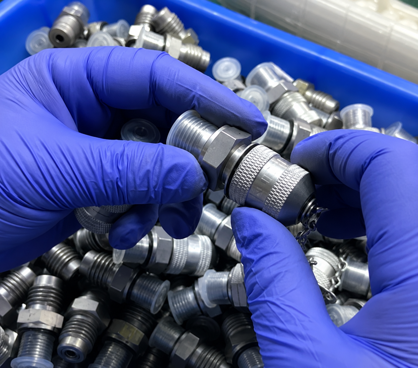
TIME manufactures eight migrated connection families, so buyers can specify an excavator test point around the machine-side geometry. Rather than a generic thread-only catalog, our drawing review verifies thread, seat, orientation and available envelope. The common error is assuming appearance alone is proof, when two interfaces are not interchangeable.
-
01 //
Bulkhead connection
Useful when the pressure-access interface must pass through a panel or bracket. Record panel thickness, hole size, thread, cap clearance and service direction.
-
02 //
DKO 24-degree cone
For selection support, review straight and DKO pressure gauge adapters when the specified connection family matches the drawing and operating conditions.
Evaluated for compatible metric tube systems. Provide tube size, cone geometry, thread and seal arrangement from the machine drawing.
-
03 //
ORFS male connection
Pairs a face-seal machine connection with a diagnostic interface. Confirm nominal size, thread, O-ring material and wrench envelope.
-
04 //
JIC 37-degree connection
Selected only after the flare seat and thread are identified. A similar appearance is not sufficient dimensional evidence.
-
05 //
Cutting-ring connection
Supports relevant metric tube layouts. Send the tube outside diameter, series, fitting geometry and intended assembly arrangement.
-
06 //
Tee connection
Adds access within a compatible line arrangement. Document all three interfaces, flow path, orientation and installation clearance.
-
07 //
Tube connection
Provides a route for a defined tube interface. Confirm tube material, diameter, wall, joint system and space for assembly.
-
08 //
Stud connection
Places the test point directly at a compatible port. Identify port thread, sealing method, installation depth and surrounding obstructions.
Drawing request: A clear machine drawing, marked-up hydraulic schematic or measured sample is more useful than a marketplace part name. ISO 15171-1 and ISO 15171-2 describe specific diagnostic-coupling scopes; neither standard replaces verification of the machine-side thread, seat and envelope. For diagnostic-end details, review our hydraulic test hose end fittings.
Compatibility chain
Port, Seal and Test-Hose Compatibility
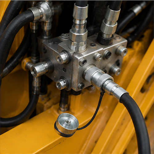
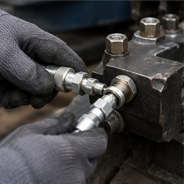
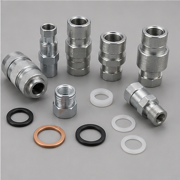
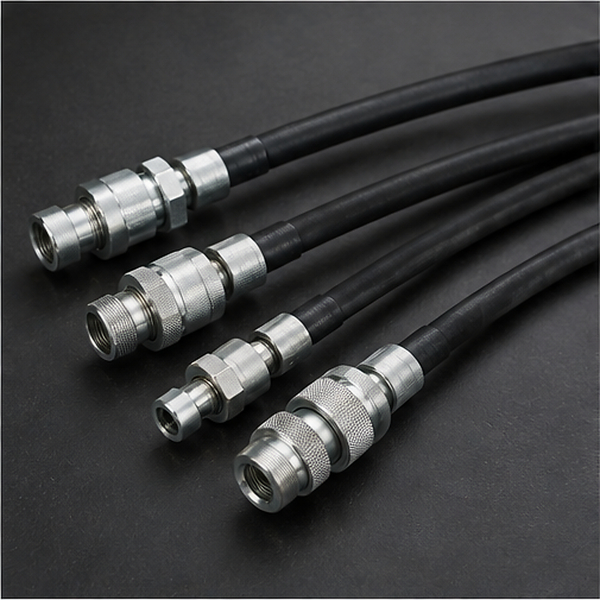
A construction equipment pressure test involves three integrated interfaces: the machine side, the test-point body and the diagnostic side. An SAE label, valve position or connector identity is not sufficient by itself; selecting the wrong seal can go unnoticed until the chain is checked ahead of hydraulic pressure testing. The distinct scopes of ISO 15171-1 and ISO 15171-2 are one reason connection-state evidence must stay attached to the exact interface.
Pressure, Material, Seal and Fluid Scope
The values below are selection inputs from legacy TIME product information or public standards. They do not characterize every possible configuration. Final values are controlled by the released part drawing and the stated application.
Connection state is a separate requirement. Working pressure, proof pressure, burst pressure and connect-under-pressure capability are different claims. A high working-pressure value is not a substitute for connection-state evidence, so do not connect a test coupling to an energized circuit unless the exact product evidence and machine procedure explicitly allow it.
Samples, MOQ and Production Lead Time
Commercial terms are confirmed in the written quotation for the part. The following planning inputs help an equipment manufacturer, distributor or fleet buyer prepare an informed application request.
Confidentiality
Your drawings are handled as confidential; confidential information is protected.
Sample timing
Samples are available in 3 days; logo customization is available.
Production
Production runs ship within 20 days after advance payment; the schedule is fixed in your quotation.
Minimum order
MOQ 300 pieces.
Reviewable evidence
Inspection, Documents and Three-Year Warranty
TIME uses a cone-seal product design and inspects every product before shipment. Our products carry a 3-year quality warranty, with the applicable terms confirmed for the order.
-
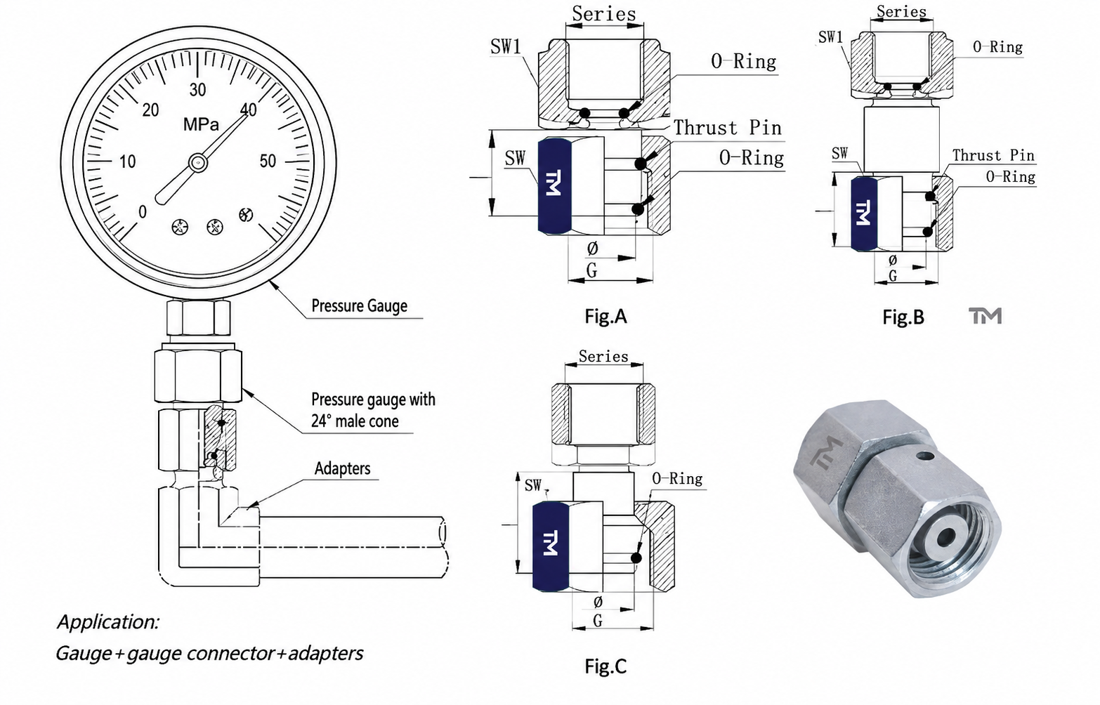
Product drawing
Defines dimensions, interfaces, material, seal and the approved configuration for buyer review.
-
Material and finish scope
Records the ordered body material, surface treatment and seal option without implying a universal specification.
-
Inspection statement
States that every product is inspected before shipment; any requested report format must be agreed before order.
-
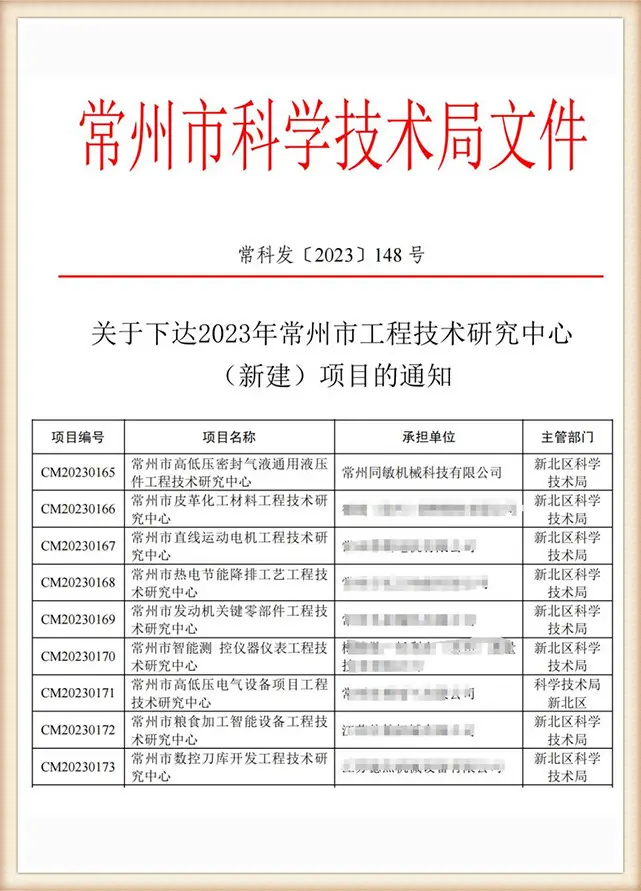
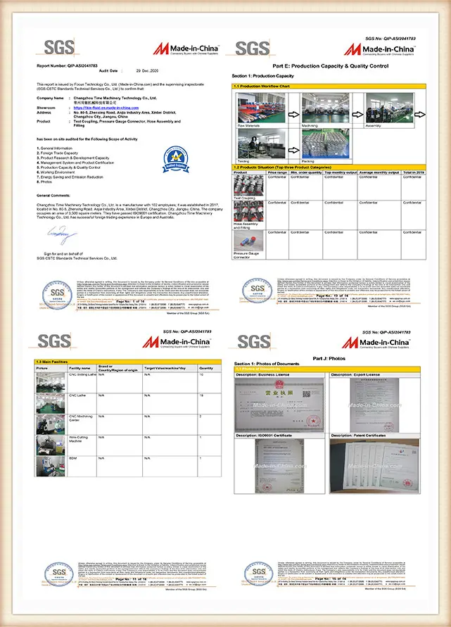
Company documents
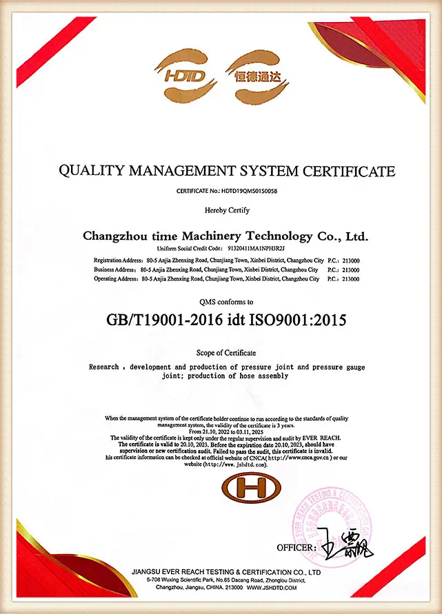
Current company or system certificates can be reviewed separately when their issuer, scope and validity are confirmed.
“A reviewable drawing and a clearly bounded claim are more useful than an unsupported compatibility slogan.”
— TIME Hydraulic Engineering Team
Evidence boundary: A matched hydraulic test point and hose do not establish gauge accuracy. Instrument range, calibration status, measurement uncertainty, test conditions and the original equipment manufacturer's procedure remain outside the component drawing unless expressly included.
Application workflow
How We Work: From Machine Data to Released Drawing
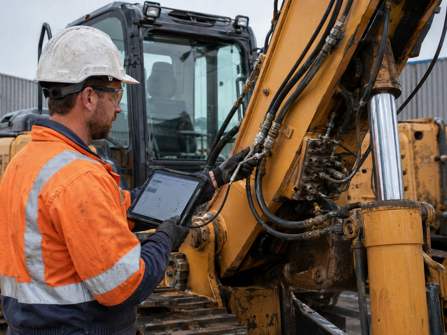
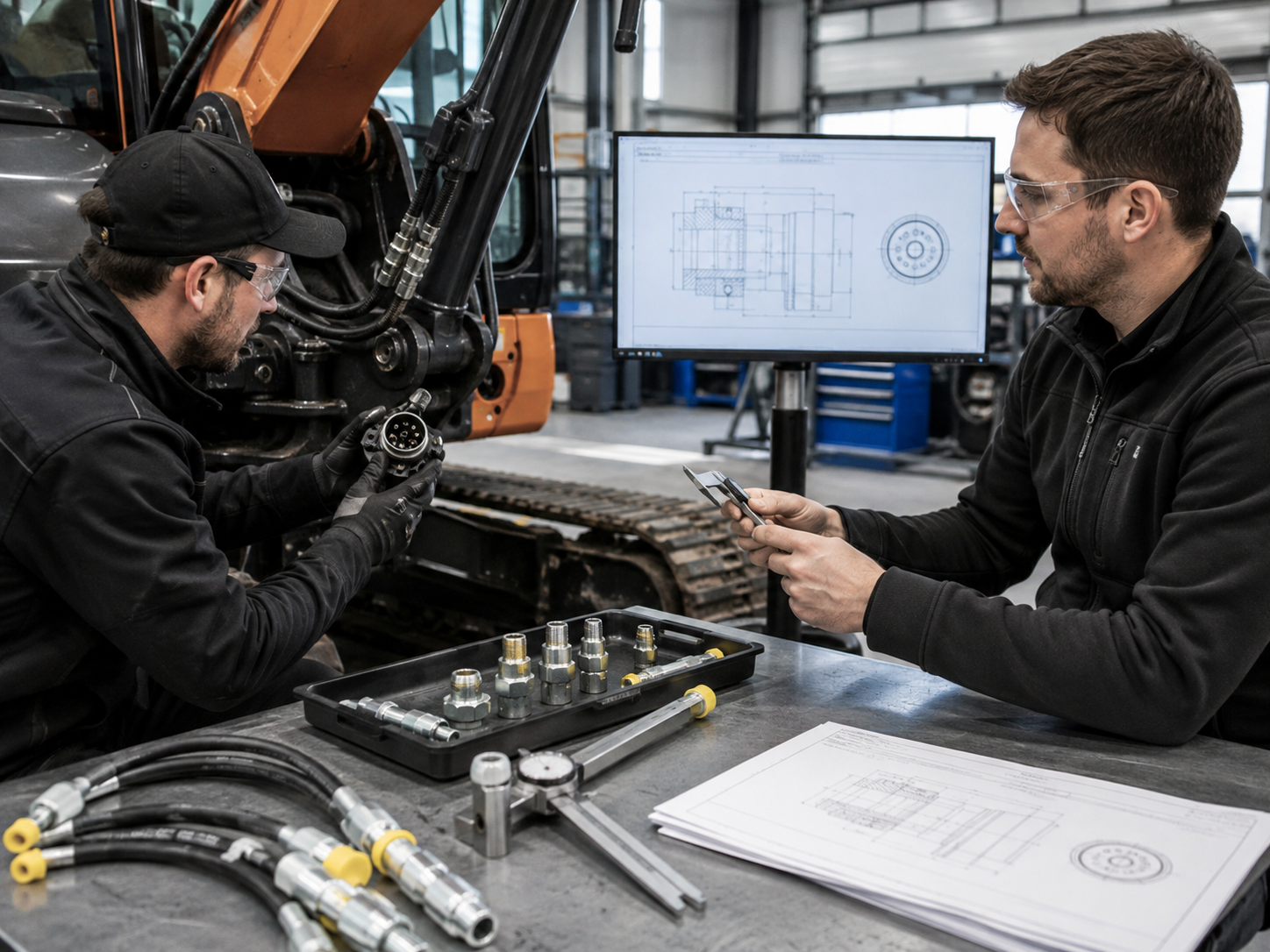
Our process converts field descriptions into a controlled component request. It does not replace the excavator manufacturer's diagnostic approach or provide machine-level approval.
01
Submit machine data
Share brand, model, serial range, circuit and the applicable schematic or procedure reference.
02
Check the interface
Our team reviews the port, seat, pressure, fluid, temperature, envelope and connection state.
03
Match the chain
TIME selects or configures the test point and aligns the coupling, hose and instrument end.
04
Review evidence
You review the drawing, specification, commercial terms and any agreed sample plan.
05
Release supply
Production, inspection and shipment follow the accepted drawing and written quotation.
Machine-to-Test-Point Request Schedule:
include machine model and serial range, circuit name, schematic reference, current thread and seal, procedure-stated pressure, fluid, temperature, hose length, gauge connection, material/finish preference and annual quantity.
TIME Hydraulic Manufacturing Focus
IKIN is our registered trademark, and TIME Hydraulic is the operating company. TIME Hydraulic manufactures hydraulic test points and hoses exclusively, providing our team with a tightly focused product and drawing vocabulary for diagnostic-access projects.
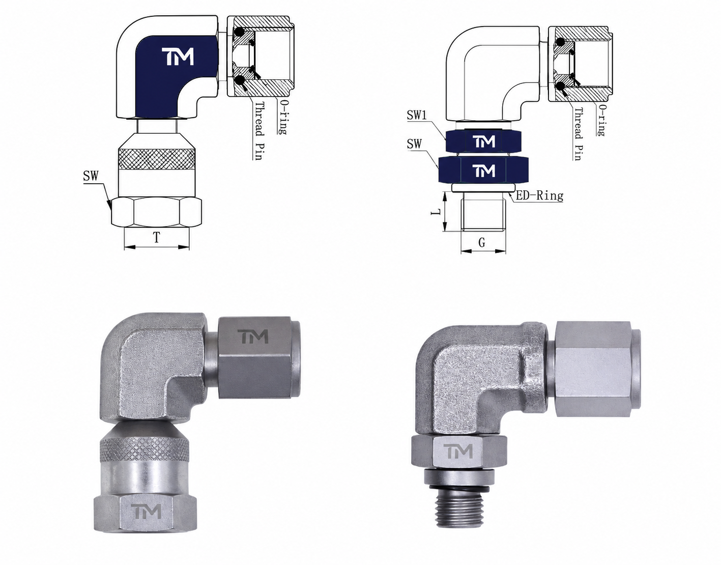
- 01 We manufacture multiple hydraulic test-point connection forms.
- 02 We pair test points with hydraulic pressure test hoses.
- 03 Our team reviews machine-side thread and seat information.
- 04 We prepare configuration-specific product drawings.
- 05 We offer carbon-steel and stainless-steel material paths.
- 06 We review seal choice against stated fluid and temperature.
- 07 We inspect every product before shipment.
- 08 Sample and logo-customization requests are supported.
- 09 Confidential drawing information is protected.
- 10 Equipment builders, maintenance supply providers and distribution teams receive application guidance.
Client-confirmed company scope
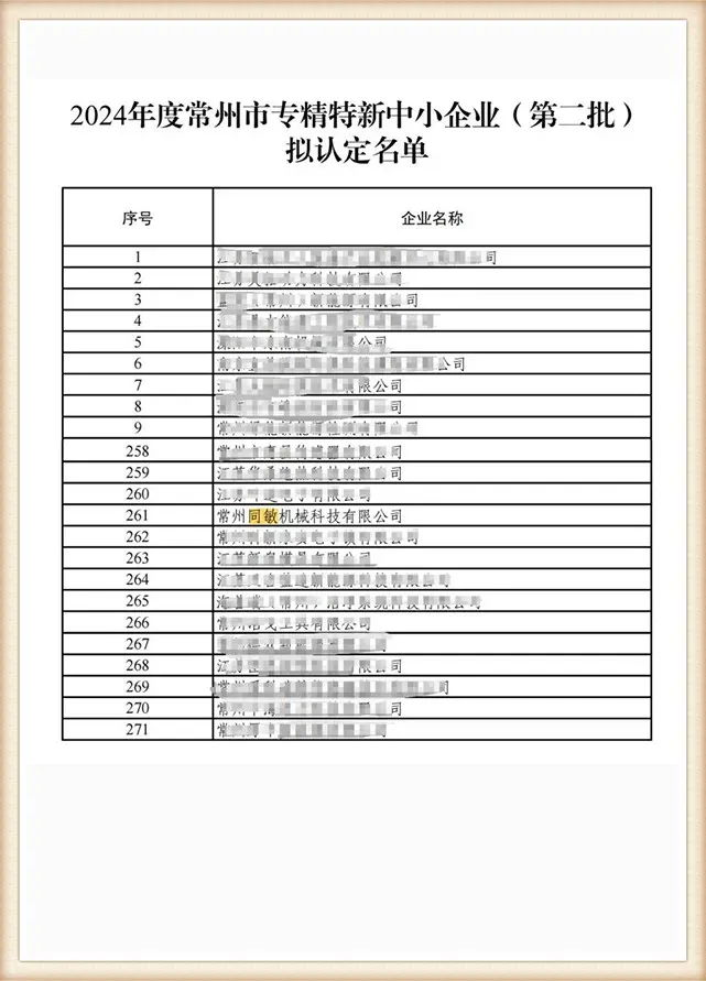
Our production facility covers 5,000 square metres, with new workshops under development. This facility statement describes the company; it does not replace product-specific drawings, inspection evidence or certification review.
Compare MPa, Bar and PSI for Your RFQApplication Boundaries and Escalation Conditions
Even with the appearance of a correct fitting, it may be unsuitable for the pressure, seal, connection state or diagnostic application. Pause selection and send the application to TIME if any item below is unresolved.
- The machine model, serial range or circuit is unknown.
- The existing port thread and seat cannot be identified from a drawing or measured sample.
- Expected pressure, fluid or temperature exceeds the scoped configuration.
- The application involves gas, non-mineral fluids, corrosive exposure or unusual low temperature.
- A universal excavator pressure test kit or diagnostic procedure is expected rather than a component drawing.
- Connection under pressure is proposed without verified product limits or a machine procedure.
- Measurement objective, gauge or sensor range or calibration state is not established.
- Caps, couplers, hose ends or test equipment cannot be kept clean before connection.
- The hose shows visible damage, has an unknown inspection state or has no verified assembly rating.
Energized hydraulic testing can expose personnel to fluid injection, hose whip and released-component hazards. ISO 4413 provides a general hydraulic-system safety framework, while the excavator manufacturer's procedure controls the machine-specific work. Follow qualified-person requirements, isolation or depressurization rules, component inspection and exclusion-zone controls; this page is a component-selection guide, not a pressure-test procedure.
Send the Application to TIME for ReviewHydraulic Engineering Tools for Excavators
Excavator Test Point Request Builder
Configure and specify exact test point requirements for OEM excavator hydraulic systems.
Open ToolHydraulic Test Chain Rating Checker
Verify pressure ratings and ensure safety compliance across your diagnostic test chain assemblies.
Open ToolHydraulic Pressure Unit Converter
Instantly convert pressure values between MPa, bar, psi, and kPa for accurate technical handoffs.
Open ToolExcavator Hydraulic Test-Point FAQs
01
What is a hydraulic test point on an excavator?
What is a hydraulic test point on an excavator?
It is a compact pressure-access component that connects a compatible hose and gauge or sensor to a defined hydraulic circuit.
02
Which excavator circuits can use hydraulic test points?
Which excavator circuits can use hydraulic test points?
Main-system, pilot, travel, swing, boom, arm, bucket, auxiliary and some return-related circuits may have defined access points. The machine schematic must first identify the circuit and access point, while the model-specific procedure must define machine state, expected measurement and connection controls. A circuit name alone cannot establish a universal port location.
03
How do I identify the existing test port or plug thread?
How do I identify the existing test port or plug thread?
Use the machine drawing, parts information or a controlled measurement of the removed component after following the manufacturer's isolation procedure. Record thread, pitch, seat or seal, depth, orientation and available wrench envelope.
04
Is M16x2 the same as every test-point interface?
Is M16x2 the same as every test-point interface?
No. M16 × 2 identifies only the thread; interface geometry, seal and qualification scope may still differ.
05
How do I match an excavator test point to a test hose and pressure gauge?
How do I match an excavator test point to a test hose and pressure gauge?
Match the machine port, test-point interface, coupling, hose ends and gauge or sensor end before comparing ratings. The lowest pressure boundary controls, while fluid, temperature, hose length, routing, instrument range and calibration status remain separate checks. State whether the target is steady-state or transient because a connected chain does not automatically produce a valid measurement.
06
Can one test point be used across different excavator brands?
Can one test point be used across different excavator brands?
Only after port geometry, seal, pressure, media, temperature, connection state and service envelope are verified for each machine.
07
What pressure rating should an excavator test point have?
What pressure rating should an excavator test point have?
The selected chain must meet the applicable machine procedure and stay within the lowest component and connection-state limit. Working pressure, proof pressure, burst pressure and connect-under-pressure capability remain separate evidence fields. A 63 MPa component cannot raise the rating of a lower-rated hose, adapter or instrument.
08
Which seal and material suit the hydraulic fluid and temperature?
Which seal and material suit the hydraulic fluid and temperature?
NBR, FKM and EPDM cover different legacy temperature ranges, while DIN 1.0718 carbon steel and 304 or 316L stainless steel provide different material paths. TIME must review the exact fluid, temperature, external environment and part geometry before release.
09
What information does TIME need to prepare a drawing?
What information does TIME need to prepare a drawing?
Send the machine brand, model, serial range, circuit, schematic reference, port thread and seat, pressure, fluid, temperature, hose length, gauge connection, material preference and quantity. Photos can support the request but do not replace critical dimensions.
10
What sample, minimum order, production and warranty terms apply?
What sample, minimum order, production and warranty terms apply?
Samples are available in 3 days, MOQ is 300 pieces, and production runs ship within 20 days after advance payment, subject to the quotation. Products carry a 3-year quality warranty, and the final order terms define the applicable scope.
