
Get in touch with TIME Company

Custom Hydraulic Test Hose Assemblies for DN2 and DN4 Test Points
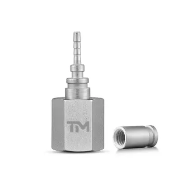
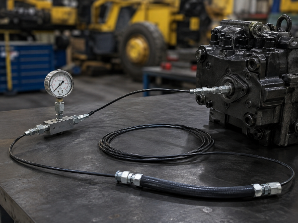
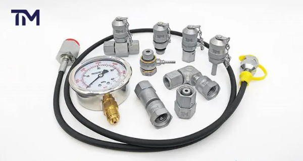
A machine has a pressure fault, a test point on the pump, and a gauge that will not reach it. We build custom test hose assemblies for that gap — microbore diagnostic lines going onto a test point at one end and your instrument at the other. Here, “test hose” means that diagnostic line, not hydrostatic proof-testing of hose as a service.
Two bore sizes cover the work — DN2 at 2 mm (0.079 in) and DN4 at 4 mm (0.157 in).
M16 × 2 diagnostic coupling, defined by ISO 15171-2:2016 — the standard fixes two separate ceilings: a maximum working pressure of 63 MPa (630 bar / 9,137 psi), and a lower limit of 40 MPa (400 bar / 5,802 psi) for connecting and disconnecting while the system is still pressurised.
- Engineer-reviewed quote within 24 hours
- Prototypes in 10 to 30 business days
- Cut to the length you specify
- Every assembly inspected before it ships
Specifications
Bore sizes
DN2 at 2 mm (0.079 in), DN4 at 4 mm (0.157 in)
Test point connection
M16 × 2 diagnostic coupling to ISO 15171-2
Pressure class
Quoted against your system pressure, to the 630 bar (9,137 psi) coupling ceiling
Assembly length
Cut to the free length between fittings that you state
Quote turnaround
Within 24 hours, reviewed by an engineer
Warranty
Three years on every assembly
CAPABILITIES
Hydraulic Test Hose Manufacturing Capabilities
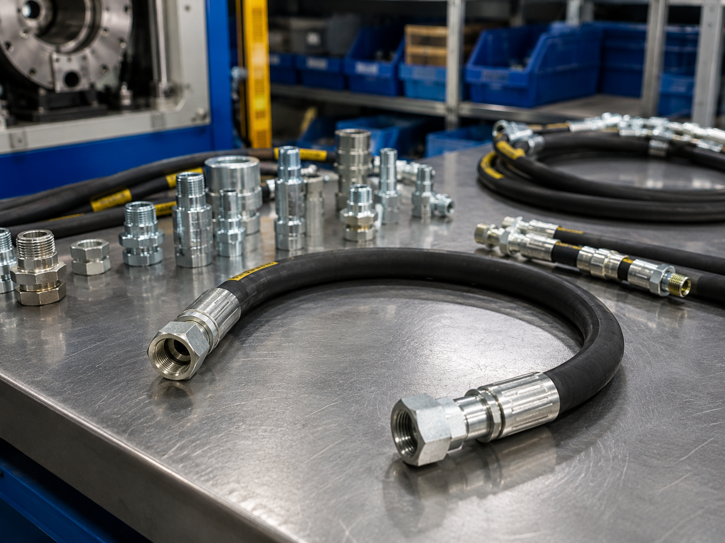
Every assembly here is built to an order rather than picked off a shelf. Four things change from job to job: the bore, the pressure class, the two end connections, and the free length between them.
Test Point End Preparation
The test point end is a cone-seal connection: the sealing face is formed on the coupling itself, so the joint seals on metal geometry rather than on a soft washer replaced at every disconnection.
Cut-to-Length Fabrication
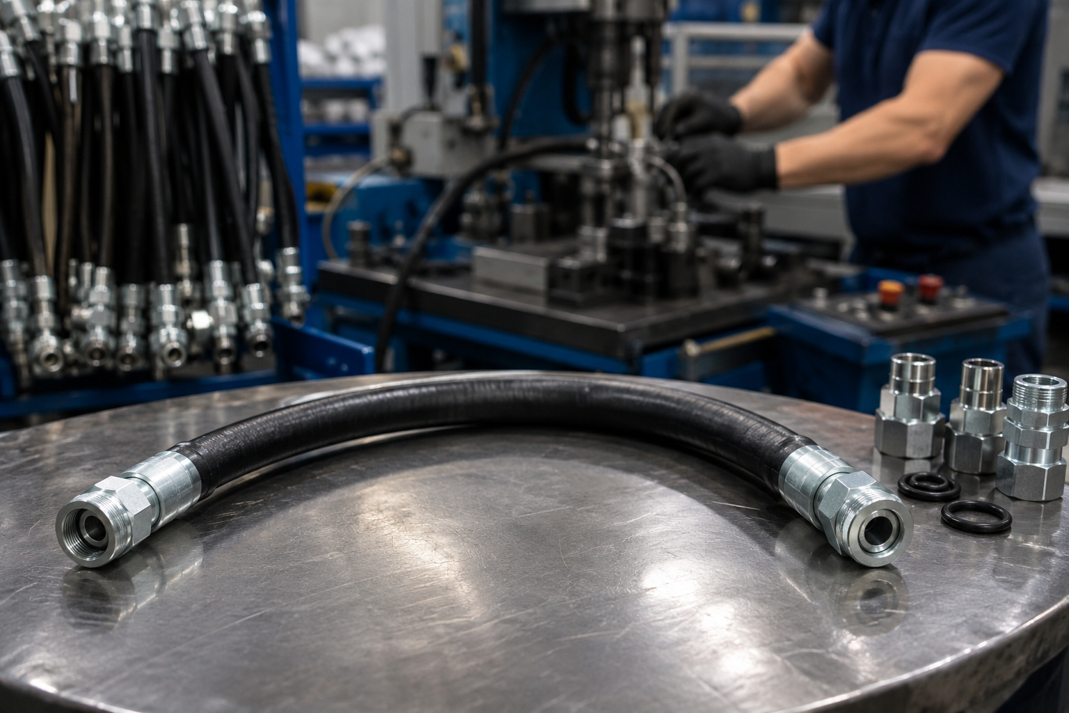
Fittings do not bend, so the dimension that matters is the free hose between them. Give us that figure and the assembly is cut and terminated to it.
Connection Matching
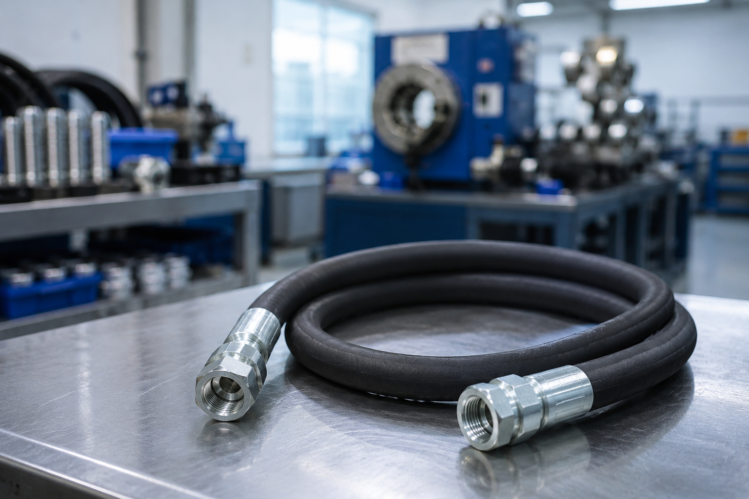
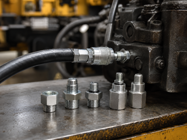
Send a thread size or a photo of the port and we identify its stud-end standard — ISO 6149-2 or ISO 9974-2 for a metric port, ISO 1179-2 for a pipe thread, ISO 11926-2 for an O-ring boss — before quoting. Where a port falls outside the diagnostic coupling family, we say so instead of quoting an adapter stack.
Per-Piece Inspection
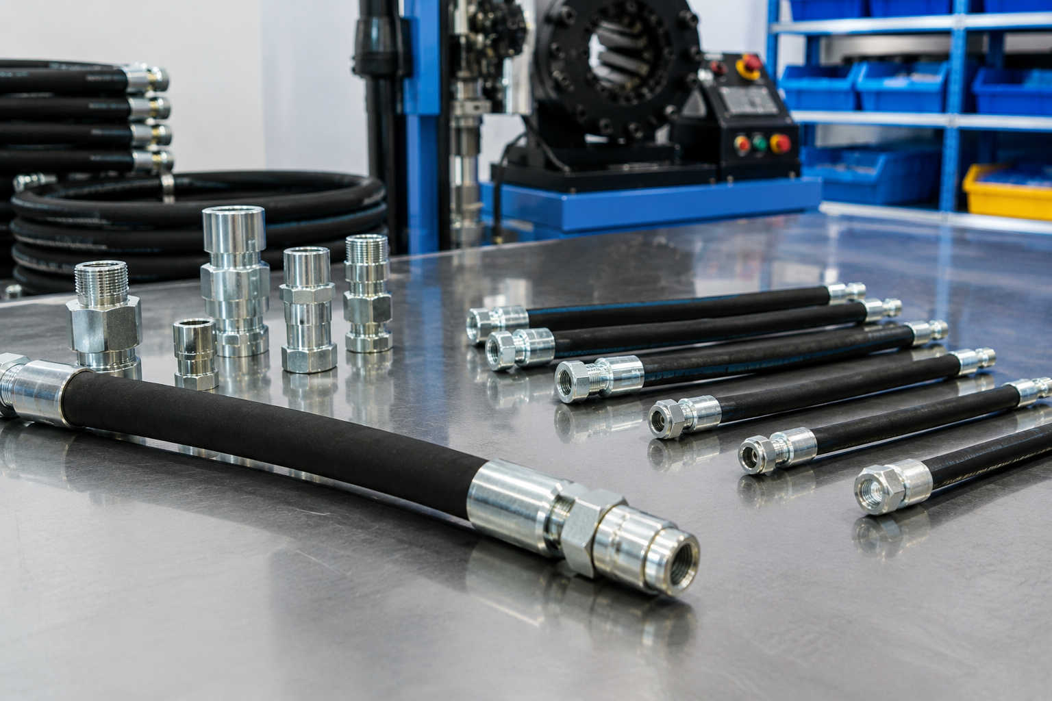
Assemblies are inspected individually before shipment against the written specification that was quoted, not sampled by batch. Acceptance criteria are fixed before the first piece is built.
PORTFOLIO
Test Hose Assemblies We Build Most Often
-
DN2assemblies for high-pressure diagnostic taps on pumps and main circuits -
DN4assemblies for gauge, transducer and instrument lines -
M16 × 2test point hose assemblies toISO 15171-2, catalogued as Test 20 -
Assemblies built to a stated free length rather than a catalogue length
-
Assemblies with a self-sealing test point at one end and a gauge connection at the other
-
Replacement assemblies matched to a thread already fitted to the machine
Hydraulic Hose Constructions and Fitting Materials
A microbore test line is a thermoplastic hose with a braided reinforcement layer, terminated in a diagnostic coupling. Three ISO specifications govern that combination, and each answers a different question: what the hose is, what the coupling is, and which of the two limits the finished assembly.
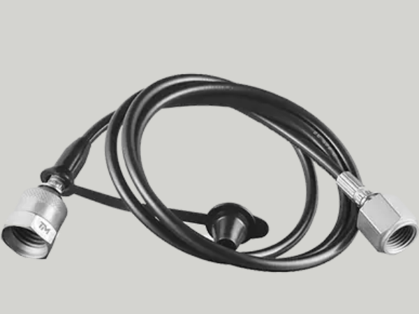
Textile-Reinforced Thermoplastic Hose
- Defined by ISO 3949:2020, three types of textile-reinforced thermoplastic hose and hose assemblies
- Nominal size range 3,2 to 25 — brackets DN4 inside the standard, leaves DN2 below its smallest size
- Oil-based fluids HH, HL, HM, HR, HV to ISO 6743-4; −40 °C to +93 °C (−40 °F to +199 °F)
- Water-based fluids HFC, HFAE, HFAS, HFB and water; 0 °C to +60 °C (+32 °F to +140 °F)
- Not covered End fittings — the standard states it includes no requirements for them
Yarn or Wire Reinforced Thermoplastic Hose
- Defined by ISO 23297:2017, eight classes in two types — with an adhesive bond between layers, and without
- Nominal size range 3,2 to 31,5; one maximum working pressure applies across all sizes in a class
- Grades A and B −40 °C to +100 °C (−40 °F to +212 °F)
- Grades C and D −40 °C to +120 °C (−40 °F to +248 °F)
- Assembly rule Assembly maximum working pressure is governed by the lowest maximum working pressure of the components
M16 × 2 Diagnostic Coupling
- Defined by ISO 15171-2:2016 — dimensions, performance and test procedures for diagnostic couplings with an M16 × 2 connection end
- Connect under pressure Without tools, to 40 MPa (400 bar / 5,802 psi)
- Maximum working pressure 63 MPa (630 bar / 9,137 psi); the standard adds that it depends on materials, design, working conditions and application
- Fluid scope Mineral-oil systems; other fluids require agreement between supplier and purchaser
- Mating ports Stud ends to ISO 6149-2, ISO 9974-2, ISO 1179-2, ISO 11926-2
Test Hose End Fittings and Test Point Compatibility
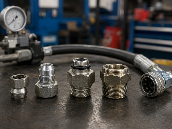
It would be simpler if every machine builder had settled on one test fitting; they did not. Open a service truck and you will quickly find NPT, JIC, O-ring boss and British straight thread in the same drawer, before anyone counts sizes. So the most common reason a test hose arrives and will not go on is that the port belongs to a different thread standard than the one assumed at ordering — and ISO 15171-2 names the stud ends the M16 × 2 coupling is built to work with, which makes this a matter of record rather than catalogue matching.
Specifications
ACTIVE MATRIX
| Connection | Thread Standard | Connect under pressure | Where it sits |
|---|---|---|---|
| Diagnostic coupling, test point end | M16 × 2 ISO 15171-2:2016 |
Yes, without tools to 400 bar (5,802 psi) | Onto the test point; catalogued as Test 20 |
| Metric stud end, O-ring seal | M14 × 1,5 ISO 6149-2 |
Through the coupling fitted to it | Machine port, newer metric equipment |
| Metric stud end, sealing ring | M14 × 1,5 ISO 9974-2 |
Through the coupling fitted to it | Machine port, same thread, different seal |
| Pipe thread stud end | G 1/4 ISO 1179-2 |
Through the coupling fitted to it | Machine port, European hydraulic blocks |
| Inch stud end, O-ring boss | 7/16-20 UNF ISO 11926-2 |
Through the coupling fitted to it | Machine port, North American equipment |
| Instrument end | Stated on your order | Matched to your gauge or transducer | No, Onto the reading device |
| Bulkhead or panel connection | Stated on your order | Matched to the panel cut-out | No, Reading point outside a guard |
| End orientation, straight or angled | Stated on your order | Set by bend clearance at the port | Not applicable, So the hose leaves the coupling unbent |
| Ports outside the four standards above | Send the thread size or a photo | Confirmed case by case | Confirmed with the port. We say whether an adapter is needed, or that the port is outside this family |
Safety Compliance
“Getting this right is a safety matter before it is a convenience. Where replacement or maintenance takes place on a pressurised system, fittings should be matched and compatible as per the original equipment manufacturers specification. Verification of such replacement should be regarded as a pressure test and appropriate precautions taken.”
— UK Health and Safety Executive, FOD 4-2014Assemblies ship with the two ends stated on the order and nothing else fitted. Adapters are quoted separately and only where one is confirmed necessary — every stacked adapter adds a joint that can weep.
Test Hose Specifications and Working Pressure Ratings
The table separates what the standards fix from what we commit to. Pressure is given in bar and psi and temperature in Celsius and Fahrenheit throughout, because the two halves of this market do not use the same units.
Specification Matrix // Active
| Specification | Value | Basis |
|---|---|---|
| Nominal bore, DN2 | 2 mm (0.079 in) | DN size designation |
| Nominal bore, DN4 | 4 mm (0.157 in) | DN size designation |
| Maximum working pressure at the M16 × 2 coupling | 63 MPa — 630 bar (9,137 psi) | ISO 15171-2:2016 |
| Connect and disconnect while pressurised, without tools | To 40 MPa — 400 bar (5,802 psi) | ISO 15171-2:2016 |
| Pressure ceiling of the finished assembly | Set by its lowest-rated component, not by the hose alone | ISO 23297:2017; EN ISO 4413 |
| Proof test pressure | Twice the maximum working pressure, unless otherwise specified | ISO 6605, hydrostatic test to ISO 1402 |
| Minimum burst pressure | Four times the maximum working pressure, unless the product specification states otherwise | ISO 6605 |
| Oil-based fluids and temperature | HH, HL, HM, HR, HV to ISO 6743-4; −40 °C to +93 °C (−40 °F to +199 °F) | ISO 3949:2020 |
| Water-based fluids and temperature | HFC, HFAE, HFAS, HFB and water; 0 °C to +60 °C (+32 °F to +140 °F) | ISO 3949:2020 |
| Fluid at the diagnostic coupling | Mineral oils; any other fluid by agreement between supplier and purchaser | ISO 15171-2:2016 |
| Assembly length | Free hose length between fittings, cut to your figure | Built to order |
| Quote turnaround | Within 24 hours, reviewed by an engineer | Our commitment |
| Prototype lead time | 10 to 30 business days after drawing approval | Our commitment |
| Production lead time | 45 to 60 business days, standard custom orders | Our commitment |
| Inspection and warranty | Every assembly inspected before it ships; three-year warranty | Our commitment |
Why There Are Two Pressure Ceilings and Not One
The 630 bar (9,137 psi) figure is what the coupling may work at once connected; the 400 bar (5,802 psi) figure is the highest pressure at which it may be pushed on or pulled off by hand while the circuit is live. Neither is a promise about the finished assembly: EN ISO 4413 requires all parts of the system to withstand pressures corresponding to the maximum operating pressure of the system or any other component, and ISO 23297 puts the same rule in product terms. A 630 bar hose behind a 400 bar coupling is a 400 bar assembly.
Reading the Machine Before Choosing the Class
Caterpillar lists the 320 medium excavator at 5,075 psi (350 bar) maximum equipment pressure and 5,510 psi (380 bar) in lift mode; the same specification footnotes its Auto Dig Boost and Auto Heavy Lift figures as 380 bar boost pressure over 350 bar standard pressure. Against a 380 bar peak, a 400 bar class leaves 20 bar of headroom, about five per cent; a 630 bar class leaves 250 bar. That arithmetic is why we ask for peak pressure rather than running pressure.
Request a Quotation
Test Point and Pressure Class Selector
Works from your port thread and peak system pressure to the connection standard and pressure class.
Open the test point selectorPressure Unit Converter
Converts bar, psi and MPa on the exact factor of 1 psi = 6,894.757 Pa, so 630 bar returns 9,137 psi rather than a rounded figure.
Open the pressure unit converterTest Hose Assembly Pricing, Quotation and Lead Time
Price follows the bore, the pressure class, the two end connections, the length and the quantity. There is no price list for made-to-order assemblies; your figure comes back in a written quotation.
Cost Drivers
| Cost driver | Effect | How to reduce it |
|---|---|---|
| Pressure class | A higher class carries a heavier construction through the whole assembly | Quote against the machine's peak pressure, not the top of the range |
| End connections | Two different, uncommon ends cost more than one repeated standard end | Standardise the instrument end across your kit so only the test point end changes |
| Length and quantity | Short runs of many lengths cost more per piece than one length in volume | Consolidate to two or three lengths that cover the routing you have |
| Special requirements | Marking, traceability and non-standard packing are separate work | State them at enquiry so they are priced once rather than added later |
Lead Time
| Order stage | Lead time | What it covers |
|---|---|---|
| Sample | Free sample, freight collect | One assembly for fit and function checking before you commit |
| Prototype | 10 to 30 business days | Built after drawing approval, to the quoted specification |
| Production | 45 to 60 business days | Standard custom orders; multi-part or highly customised orders take longer |
Send a drawing, a thread size or a photo of the port, and an engineer returns a quotation within 24 hours. Quotes are reviewed by a person rather than produced by a configurator, which is why we can tell you when the connection you asked for is the wrong one.
When the clock starts
Lead time starts at drawing approval and excludes transit. Rush orders are accommodated where feasible, with the schedule impact confirmed once the drawing and quantity are reviewed.
Minimum order quantity
Minimum order quantity starts at 100 pieces for standard items and at 500 to 1,000 pieces for fully custom assemblies. We accept smaller trial orders; an order below USD 15,000 in value carries a USD 350 handling charge.
Payment and shipping terms
Payment is by bank transfer with a 30 per cent deposit and the balance before shipment, negotiable on repeat orders. We ship FOB Ningbo or Shanghai, or Ex Works, and quote CIF or DDP on request.
Test Hose Inspection, Pressure Ratings and Warranty
Safety Critical Context
A test hose assembly is a safety component that spends its life being connected and disconnected on live machines, so this section covers what we do and what the standards fix about the pressure figures printed on it. The failure being controlled is specific: a hose that leaks or separates at the coupling does it with the circuit live and a person standing at the machine. Two things put an assembly there — a crimp diameter outside the range the hose-and-coupling combination was qualified at, and a maximum working pressure taken from a burst ratio instead of read from the assembly's own rating.
Our inspection and release rule
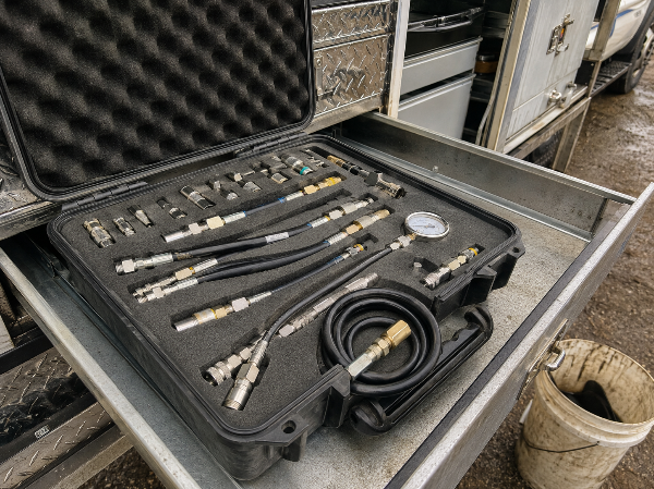
- Drawing review before anything is cut — port standard, pressure class, fluid and free length confirmed in writing, and that document becomes the specification we are held to.
- Component pressure classes checked against your system pressure, because the assembly is governed by its lowest-rated part rather than by its hose.
- Every assembly inspected individually before shipment against that written specification, with no batch sampling.
- Released only against the criteria that were quoted, so nothing is judged afterwards by a standard nobody agreed to.
Nothing ships on a batch average. Every assembly is inspected individually against the written specification that was quoted, and one that does not meet it is replaced under the three-year warranty.
Verification Points Worth Putting to Any Supplier
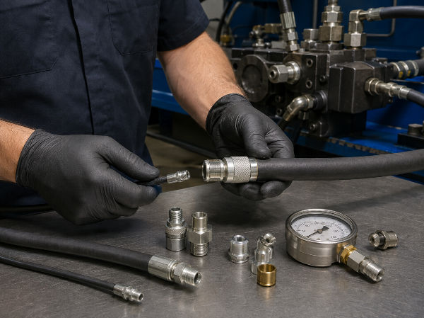
These separate a qualified hose-to-coupling interface from a merely crimped one, and apply to us as much as to anyone else quoting you.
- Whether crimp diameter is measured at each end and compared against a qualified range, rather than one setting being assumed to hold
- Whether a go/no-go gauge is used, and against which range
- Whether the hose-and-coupling combination was qualified by burst and impulse testing across a range of crimp diameters rather than at a single nominal value
- Whether that testing ran at the temperature the application sees
- Whether couplings from different makers are treated as equivalent, when steel grade, hardness and serration geometry differ between them
Send these points with your enquiry and we answer them in writing before you order. Every assembly carries a three-year warranty; if one does not meet the specification on your order, tell us and we replace it under that warranty.
ISO Standard Protocol
What the Standards Fix About the Pressure Figures
ISO 6605 defines a proof test as a hydrostatic pressure test to ISO 1402 at twice the maximum working pressure, unless otherwise specified, with assemblies showing no leakage passing. It sets minimum burst pressure at four times the maximum working pressure — again unless the product specification states otherwise, and microbore test hose is exactly the family where specifications do. So read the stated maximum working pressure of the assembly you are buying rather than deriving it from a ratio.
Custom Test Hose Assembly Ordering Process
Thread size or a photo of the port, peak system pressure, fluid, and the length you need.
We confirm the stud-end standard, the pressure class the machine requires, and the end orientation the routing allows.
Returned within 24 hours by an engineer, specification written out rather than implied.
A free sample with freight collect, or a prototype in 10 to 30 business days after approval.
Every assembly inspected before it ships, and the result is ours to answer for against the quoted specification.
On the terms quoted with your price.
STAMPED is the seven-point checklist the fluid power industry uses to specify a hose assembly. It is neither ours nor new — it is the order the questions have to be answered in, and it maps onto this page one letter at a time.
| Letter | What it decides | What we need from you | Answered here |
|---|---|---|---|
| S — Size | Bore and length: DN2 at 2 mm (0.079 in) or DN4 at 4 mm (0.157 in), and the free length between fittings | The reading you need and the routing distance | Specifications |
| T — Temperature | Whether fluid and ambient temperatures sit inside the construction's envelope | Running oil temperature and the ambient | Constructions |
| A — Application | Permanent gauge feed, or a diagnostic line connected under pressure | How often it is connected, and whether the circuit is live | Applications |
| M — Material and media | Whether the fluid is a mineral oil, which the coupling is designed for, or one needing agreement | The fluid by name, not by colour | Limits |
| P — Pressure | The class, checked against peak pressure and surges rather than steady running pressure | The machine's peak or boost pressure figure | Pressure ratings |
| E — Ends | The port standard at the machine and the connection at the instrument | Thread size or a photo of the port, and your gauge connection | Compatibility table |
| D — Delivery | Quantity, date, marking and any certification the order must carry | Quantity, required date, documentation | Lead times |
| Design feature | What to specify | Why it saves money |
|---|---|---|
| Adapter stacks | The port thread you actually have, so the assembly ends in it directly | Each stacked adapter is a purchased part and a joint that can leak |
| Length datum | Free hose length between fittings, not overall length across the couplings | Removes the most common cause of a second, corrected order |
| Bend at the coupling | An angled end where the hose must turn immediately at the port | Stops the hose being bent at its stiffest point, where failures start |
| How the part is called out | Working pressure, temperature and fluid — not "same as the old one" | Ordering by construction reproduces a mistake instead of meeting the system requirement |
STAMPED Specification Sheet
Fill in the seven fields and it produces the enquiry text to paste into your request, so nothing is left for us to assume.
Limits of Microbore Test Hose Assemblies
There are jobs a microbore test line does not do, and cases where it is the wrong thing to reach for. Naming them at drawing review is the trade-off worth making: a line specified against the wrong condition is not interchangeable with one specified against the right condition, and finding that out at the machine costs you months rather than days. Each case below carries the risk it creates, and the right call to make instead.
Situation 01
The fault is speed or force, not pressure
Why it works against you
A test point reads pressure only, and a pressure reading does nothing for a speed or force complaint. A machine can show correct static pressure at the port and still be slow or weak through a working cycle — pressure and flow are not the same measurement.
What to do insteadPut a flow meter in the circuit and use the test hose to confirm pressure at the same moment, so both readings come from one load condition.
Situation 02
The line sits at sustained high oil temperature
Why it works against you
ISO 3949 puts oil-based fluids at −40 °C to +93 °C (−40 °F to +199 °F). In one measured study of a closed-circuit hydraulic system, oil temperature approached its 80 °C (176 °F) design setpoint without exceeding it — on a machine running that hot, the margin left to the +93 °C ceiling is thinner than the nameplate suggests.
What to do insteadGive us the running temperature at drawing review and the construction is quoted against it rather than against room temperature.
Situation 03
The fluid is not a mineral oil
Why it works against you
ISO 15171-2 designs the M16 × 2 coupling for mineral-oil systems and moves every other fluid to agreement between supplier and purchaser — a scope boundary in the standard, not a preference.
What to do insteadName the fluid. Phosphate ester, water glycol and biodegradable fluids are quoted case by case against seal and liner materials.
Situation 04
The test point is opened in a dirty environment
Why it works against you
Spool-to-body clearance is measured in microns. Peer-reviewed testing found contaminated friction rising sharply once particle size reaches 0.7 to 0.9 times that clearance, and complete stagnation — the spool stopping — once particle size equals the clearance.
What to do insteadKeep the coupling face capped between readings and use self-sealing test points, so the circuit is never opened to the air to take a measurement.
Test Hose Assembly Tools
Pressure Unit Converter
Instantly convert between bar, psi, MPa, and other standard hydraulic pressure units. Ensure precise parameter matching for your diagnostic operations.
Open Tool
Stamped Spec Sheet
Generate and download formalized specification sheets for custom hose assemblies. Includes detailed technical parameters for OEM procurement and verification.
Open Tool
Test Point Selector
Identify and configure the exact test point couplings for your system requirements. Cross-reference thread types, sealing forms, and pressure ratings.
Open Tool
Hydraulic Test Hose FAQs
What is a microbore hose?
A microbore hose is a small-bore hydraulic hose carrying pressure to an instrument rather than power to an actuator. Here that means a 2 mm or 4 mm inside diameter — small enough that the fluid barely moves, which is what makes an accurate static pressure reading possible.
What is the DN notation for hose sizing, and is -02 hose the same as DN02?
DN is a metric nominal-bore designation in millimetres, so DN2 is a 2 mm bore and DN4 a 4 mm bore. Dash sizes on power hose count sixteenths of an inch, so -02 is a one-eighth inch bore. Different systems; the numbers do not translate.
How do I choose between DN2 and DN4 microbore test hose?
DN2 at 2 mm bore suits high-pressure diagnostic taps where only a pressure signal has to reach the gauge; DN4 at 4 mm bore suits instrument and transducer lines where the connection is more permanent. Send the peak system pressure and the instrument you are feeding, and we say which one the job takes.
Which test point couplings are compatible with M16x2 (Test 20) ends?
ISO 15171-2 names the stud ends the M16 × 2 coupling works with: ISO 6149-2 and ISO 9974-2 at M14 × 1,5, ISO 1179-2 at G 1/4, and ISO 11926-2 at 7/16-20 UNF. The full matrix, including ports outside this family, is in the compatibility table.
Why do proof pressure and working pressure differ, and can I run a hose at its proof pressure?
No. ISO 6605 defines proof pressure as a factory hydrostatic pressure test at twice the maximum working pressure, applied once to show the assembly does not leak. That is a test condition, not an operating permission — the figure an assembly may work at continuously is its stated maximum working pressure.
What working pressure rating do I need for my test point?
Take the machine's peak figure, not its running figure. Caterpillar lists the 320 at 5,075 psi (350 bar) equipment pressure and 5,510 psi (380 bar) in lift mode; against that 380 bar peak a 400 bar class has 20 bar of margin while a 630 bar class has 250 bar. EN ISO 4413 also asks that systems be designed and configured to minimise pressure surges, and that a surge must not give rise to a hazard — so the class has to sit above the spikes, not just above the running figure.
What temperature and fluid can a test hose handle?
For textile-reinforced thermoplastic hose, ISO 3949 gives −40 °C to +93 °C (−40 °F to +199 °F) on oil-based fluids to ISO 6743-4, and 0 °C to +60 °C (+32 °F to +140 °F) on water-based fluids and water. The coupling itself is designed by ISO 15171-2 for mineral-oil systems, and any other fluid is a matter for agreement between supplier and purchaser.
What causes a test hose to fail, and when should it be replaced?
Most failures start at the coupling neck, from bending the hose where it leaves the fitting, or from abrasion against a moving part. Replace on any sign of weeping, cover damage or a coupling that no longer seats cleanly: the Health and Safety Executive records that although serious reported injection injuries have occurred at pressures over 100 bar (1,450 psi), anecdotal evidence suggests injury may occur at pressures as low as 7 bar (101.5 psi). Depressurise before handling any component, never run a hand along a hose to find a leak, and treat any skin puncture as an emergency.
Can you make test hose assemblies to a custom length?
Yes — length is the variable these assemblies exist for. Specify the free hose length between the two fittings rather than the overall length across the couplings, because the fittings do not bend.
What do you need from me to quote?
The port thread or a photo of the test point, the machine's peak system pressure, the fluid, the free length and the quantity. That is enough for a written quotation inside 24 hours; a drawing speeds it up but is not needed to start.
