
Get in touch with TIME Company

DN4 Hydraulic Test Hoses — High-Flow Test Point Assemblies | TIME Hydraulic
- Quotes returned within 24 hours on business days
- Standard build 4–6 weeks after specification confirmation
- 630 bar (9,137 psi) maximum working pressure
- Direct fit to Minimess, Stauff, MCS and Minipress test points
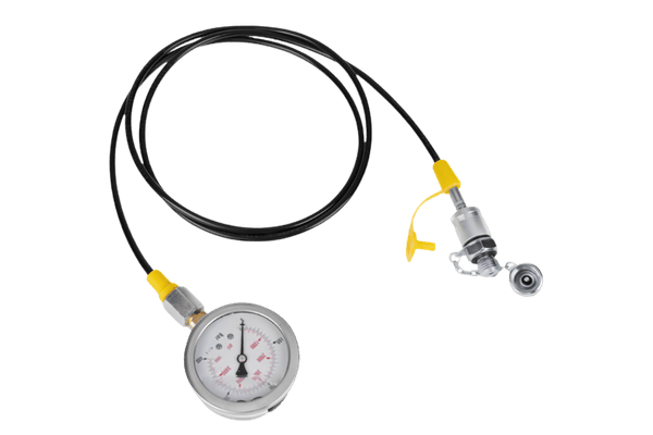
We build DN4 hydraulic test hose assemblies for pressure diagnostics on live circuits, in six end configurations and in BSP, NPT, JIC and metric threads cut to your drawing. Every assembly mates with the ISO 15171-2 test point family — the coupling type designed to be connected and disconnected while the system stays pressurised — and is rated to 630 bar (9,137 psi) maximum working pressure. Send a drawing, a part number, or a photo of the port you are measuring, and an engineer comes back with a quote.
Nominal bore
DN4 — 4 mm (0.157 in) inside diameter
Maximum working pressure
630 bar (9,137 psi) on our DN4 assemblies
Test point thread
M16 × 2, the Test 20 / 1620 pattern
Quote turnaround
Returned within 24 hours on business days
Build time
4–6 weeks after specification confirmation
Order size
No fixed minimum — single pieces are accepted
DN4 Test Point Hose Assembly Configurations
Our DN4 hydraulic test hose is the largest member of the microbore diagnostic hose collection — a 4 mm bore line that carries pressure from a test point to a gauge, transducer or data logger without opening the circuit. It’s not a miniature hydraulic hose: the bore, the coupling and the seal are specified for measurement rather than for power transmission. We’ll build it to suit the end configuration already on your machine, so the hose just plugs into the port without forcing an adapter stack.
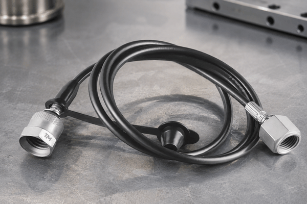
Straight male stud
What it is
A fixed male thread that screws into the port and stays there for the life of the assembly.
Where it earns its placePermanent gauge lines on pumps, filters and manifold faces.
Test point coupling
What it is
The push-on coupling half that mates with an installed test point and seals through an internal poppet.
Where it earns its placeService and diagnostic work where the hose moves from point to point.
Banjo (swivel elbow)
What it is
A bolted swivel head that lets the hose leave the port sideways at any clock position.
Where it earns its placePorts buried under castings, guards or adjacent hose runs.
DKO 24° cone
What it is
A metric 24° cone seat, tightened metal-to-metal or with an elastomer insert.
Where it earns its placeEuropean machine builds already standardised on DKO ports.
O-ring face seal
What it is
A flat face carrying an O-ring, clamped by a captive nut.
Where it earns its placeHigh-vibration mounts where a cone seat works loose.
Gauge-fitted assembly
What it is
The hose supplied with the pressure gauge already mounted and leak-checked as one unit.
Where it earns its placeField kits and hand-over sets where the crew should not be sourcing gauges.
Thread Systems We Cut
BSP parallel:
G1/4, G3/8 and G1/2, sealed on a bonded washer or a cone seat.
NPT taper:
1/8-27, 1/4-18 and 3/8-18, for machines built to the North American port convention.
JIC 37° flare:
including 7/16-20 UNF, the smallest of the four stud ends ISO 15171-2 permits on a test point.
Metric:
M14 × 1.5 and M16 × 1.5 stud ends, plus the M16 × 2 coupling thread that the Test 20 and 1620 designations both describe.
ISO 15171-2 fixes four permitted stud ends for this coupling family: M14 × 1.5 to ISO 6149-2, M14 × 1.5 to ISO 9974-2, G1/4 to ISO 1179-2, and 7/16-20 UNF to ISO 11926-2. Anything outside that set is a port adapter question rather than a test point question, and we quote it as such. Tell us the port and we confirm which of the four it maps to.
Fitting Minimess, Stauff, MCS and Minipress Test Points
Buyers rarely search for this part by brand. On engineering forums the working advice is to search the standard name instead — “try using the term ‘minimess’ when searching as this is a kind of standard test point connector specification” — which is exactly why a hose sold under one brand has to physically fit points installed under another. Our DN4 assemblies are built to mate with Minimess, Stauff, MCS and Minipress test points already in service — but M16 × 2 and M16 × 1.5 points are not interchangeable, so the thread is the check that settles it.
| What to check | What you are looking at | Why it decides the fit |
|---|---|---|
| Coupling thread on the point | M16 × 2 is the Test 20 and 1620 pattern; M16 × 1.5 is the 1615 pattern. | Half a millimetre of pitch is the single most common reason a hose arrives and will not seat. |
| Cap and dust seal | Screw cap, chain-retained cap, or an open point with no cap at all. | Tells you whether the point is a permanent installation or a temporary tapping. |
| Stud end into the machine port | The thread on the far side of the point, into the pump, valve or manifold. | Decides whether you order a hose only, or a hose plus a replacement point. |
| Gauge end | Thread size and whether the gauge is bottom-entry or back-entry. | Sets the swivel and the elbow, and whether we supply the gauge fitted. |
Not sure which pattern is on your machine?
Test Point Identifier
A brief guide that walks through the four checks above in sequence and returns the coupling thread, the matching hose end and the questions worth asking your supplier.
Hose and Fitting Materials
A test hose is a small assembly with six material decisions in it, and each one is set by something on your order rather than by a house default. Mineral-oil hydraulic systems are the default fluid scope, which is the same default ISO 15171-2 works from; any other fluid is confirmed by agreement between supplier and purchaser before we quote. Each card below says what that part does and what you need to state so we build the right one.
What it does
Carries the fluid at pressure and sets the chemical compatibility of the whole assembly.
What you specifyThe fluid by name, and the peak fluid temperature at the test point rather than in the reservoir.
Default scopeMineral-oil hydraulic systems; other fluids confirmed by agreement.
What it does
Carries the hoop load, so it is what actually sets the pressure class of the finished hose.
What you specifyThe peak system pressure including spikes, not the gauge reading you expect to see.
Default scopeBuilt to the 630 bar (9,137 psi) class on our standard DN4 assemblies.
What it does
Takes the abrasion from rubbing against structure, and shields the reinforcement from oil and weather.
What you specifyWhether the hose lives coiled in a toolbox or clipped permanently along a boom.
Default scopeAbrasion-resistant cover; a spring guard or sleeve is quoted where the run is exposed.
What it does
The volume choice for machine-mounted assemblies, with corrosion protection applied as a coating system.
What you specifyCoating system, minimum coating thickness, and the corrosion-resistance class to ISO 19598.
Default scopeCr(VI)-free passivated electroplated zinc unless your drawing calls out another system.
What it does
Removes the coating from the equation entirely, because the corrosion resistance is in the base metal.
What you specifyWhether the exposure is salt spray, washdown chemistry, or continuous humidity.
Default scopeQuoted on request for marine, offshore, food-plant and coastal installations.
What it does
Holds the poppet and the cone or face joint tight through every connect and disconnect cycle.
What you specifyFluid and the temperature band the point actually sees in service.
Default scopeSelected against the fluid and temperature on your order, and stated on the quotation.
Corrosion Protection and OEM Marking
Corrosion protection on a test hose is a purchasing specification, not a finish you pick by colour. Each system below is defined by a published standard, and each standard gives you specific variables you can write onto an order. Column four is what to put in writing so the assembly you receive matches the one you priced.
| Protection system | Standard | What the standard fixes | What to write on your order |
|---|---|---|---|
| Electroplated zinc and zinc-alloy coatings | ISO 19598:2016 | Coatings of zinc, zinc-nickel and zinc-iron on iron or steel, with Cr(VI)-free passivation. | Coating system designation, minimum corrosion resistance under a specified test procedure, and minimum coating thickness. |
| Non-electrolytic zinc flake coating | ISO 10683:2018 | Zinc flake systems for steel fasteners, in three orderable variants: with or without hexavalent chromium, with or without top coat, with or without lubricant. | Which of the three variants you need. The standard notes this class is used on high-strength fasteners at tensile strengths of 1 000 MPa and above to avoid internal hydrogen embrittlement, and that it does not apply to mechanical zinc coating. |
| 316 stainless, uncoated | — | No coating system to specify, because corrosion resistance sits in the base metal. | The exposure you are protecting against, so we quote the right grade of hardware around it. |
| Salt spray (fog) testing | ASTM B117-26 | The apparatus and the procedure for running a salt fog exposure — and nothing else. | The exposure duration and the acceptance criterion you want us to test to, because the standard deliberately leaves both to the purchaser. |
| Part identification and OEM marking | SAE J846_202303 | A coding system for identifying fluid conductors and connectors, for use where the drawing is not readily available at the point of need. | Your own part number and any code you want laser-marked or tagged on the ferrule. |
What a Salt Spray Hour Actually Buys You
Hours in a salt fog test are quoted as a durability score, and the surprising part is that this is not what the test measures. ASTM B117-26 states that prediction of performance in natural environments has seldom been correlated with salt spray results when those results are used as stand-alone data, and it declines to specify specimen type, exposure period or interpretation of results for any particular product. It also records that results vary between cabinets running nominally identical conditions.
Writing a Salt Spray Requirement You Can Check
Therefore a salt spray score is a useful acceptance criterion and nothing else. Write it as "coating system X, tested to ASTM B117 for Y hours, accepted at Z" and it is something both parties can verify on receipt. Comparing two different coating chemistries based on hours alone is comparing two numbers that were never designed to be compared.
Marking Your Own Part Numbers
We apply OEM marking to your part number on the ferrule or on a fitted tag, so assemblies land in your stores under the code your system already knows. SAE J846 gives a recognised coding system you can specify for that marking, and the standard is explicit that adopting it is the user's choice and that it does not supersede an identification system you already run. If you have an internal scheme, we mark to yours.
DN4 Specifications and Pressure Ratings
DN4 designates a nominal bore of 4 mm. It is a size designation, not a pressure class, and that single fact is behind most of the confusion in this category. Below is what we build; the two sections after it explain how to read the pressure figures on anybody's datasheet, including ours.
| Specification | What we build |
|---|---|
| Nominal bore | DN4 — 4 mm (0.157 in) inside diameter |
| Maximum working pressure | 630 bar (9,137 psi) on our DN4 test hose assemblies |
| Coupling standard | ISO 15171-2 test point couplings — the family designed for connection and disconnection while the circuit stays pressurised |
| Test point thread | M16 × 2 as standard, the pattern also written as Test 20 or 1620; M16 × 1.5 on request |
| Permitted stud ends | M14 × 1.5 (ISO 6149-2), M14 × 1.5 (ISO 9974-2), G1/4 (ISO 1179-2), 7/16-20 UNF (ISO 11926-2) |
| Thread systems on the instrument end | BSP, NPT, JIC and metric threads cut to your drawing |
| End configurations | Six end configurations: straight male stud, test point coupling, banjo, DKO 24° cone, O-ring face seal, gauge-fitted |
| Fluid scope | Mineral-oil hydraulic systems as standard; other fluids confirmed by agreement between supplier and purchaser |
| Burst pressure, bend radius and length tolerance | Fixed by the hose construction quoted for your order and stated in writing on the quotation |
| Inspection | 100% outgoing inspection, no sampling |
| Warranty | 3 years from shipment |
| Standard build time | 4–6 weeks after specification confirmation |
The Two Pressure Numbers on a Test Hose Datasheet
Test point assemblies carry two separate pressure figures, and a datasheet often prints both without labelling which is which. One describes what the assembly holds in service; the other describes what it will let you do while the machine is running. Reading the wrong one is how a buyer ends up comparing quotations that are not comparable.
| Figure | What it describes | What to ask for in writing |
|---|---|---|
| Maximum working pressure | The pressure the assembly is rated to hold in service. ISO 15171-2 puts the ceiling for this coupling family at 63 MPa (630 bar / 9,137 psi) and makes that figure conditional on material, design, service conditions and application. | The configuration the figure applies to, since end type and seal choice both move it. |
| Connection under pressure | What the coupling will do while the circuit is live. ISO 15171-2 is the part of the standard written for couplings connected and disconnected under pressure; ISO 15171-1 covers couplings that are not designed for it. Published figures for this operation sit below the working rating — one manufacturer's DN2 range lists 400 bar (5,802 psi) against a 630 bar (9,137 psi) working rating. | The connect-under-pressure figure, stated separately from the working pressure, for the end configuration you are ordering. |
Why Two Hoses Both Marked DN4 Can Sit a Class Apart
Assemblies marked DN4 are on sale at working pressures that differ by nearly a factor of two. Contrary to the common assumption that the designation carries a rating with it, that is not a labelling error — it is what happens when a bore designation gets read as a pressure class. Three classes are in circulation.
| Working pressure class marked DN4 | In bar and psi | What it changes for you |
|---|---|---|
| 340 bar class | 340 bar (4,931 psi) | Adequate for low and medium-pressure circuits. Below the peak on most mobile machinery, so check the relief setting before you accept it. |
| 500 bar class | 500 bar (7,252 psi) | Covers the majority of mobile and industrial peaks, and is where separately quoted test and burst figures start appearing on datasheets. |
| 630 bar class | 630 bar (9,137 psi) | The ceiling ISO 15171-2 names for this coupling family. This is the class our DN4 assemblies are built to. |
In practice the consequence is simple. Two quotations both showing "DN4" may be a pressure class apart and may have one of two pressure figures printed, which means there is no real comparison to be had until you have both figures from both sources. State the working pressure and the connect-under-pressure figure as two separate figures and it becomes real.
Pressure Class Reader
Paste the two figures from any datasheet to verify the class.Quoting, Lead Time and Order Terms
Price follows the end configuration on each end, the hose length, the pressure class and the order quantity. There is no fixed price list for test hose assemblies, because two hoses of the same bore and length can carry entirely different hardware. Your figure comes back in a written quotation against the specification you send.
What Moves Your Price
| Driver | Effect on cost | How to reduce it |
|---|---|---|
| End configuration on each end | The largest single driver. A banjo or a gauge-fitted end carries more machining and more assembly time than a straight stud. | Standardise on one or two end types across the fleet instead of ordering one of everything. |
| Fitting material | 316 stainless hardware sits well above plated carbon steel on the same geometry. | Reserve stainless for the points that actually see salt, washdown or continuous humidity. |
| Length spread | Every distinct length is a separate setup, so ten lengths of ten pieces cost more than one length of a hundred. | Round your lengths into a short standard set and order the set. |
| Order quantity | Setup is amortised across the run, so the unit price falls in brackets rather than smoothly. | Ask for the bracket prices with the quote and order at the nearest break. |
How Your Quote Is Produced
Quotes are returned within 24 hours on business days, reviewed by an engineer rather than generated from a table. Specifications that need engineering review take longer, and we tell you that at intake instead of letting the clock run. There is no instant quoting engine here, which is the point: a person reads your port callouts before a number goes out.
Lead Time by Order Stage
| Order stage | Lead time | What it covers |
|---|---|---|
| Sample | Quoted with the sample request | Samples are provided at no charge for standard builds; the requester covers international courier freight. |
| First production order | 4–6 weeks after specification confirmation | Hardware, hose, assembly, 100% outgoing inspection and packing to your marking scheme. |
| Repeat order | 4–6 weeks, confirmed and locked at quotation | The same build against the frozen specification from your previous order. |
Lead time starts when the specification is confirmed, not when the enquiry arrives, and it excludes transit. Order size is not a barrier at the front end: there is no fixed minimum for standard test hose builds, and single pieces are accepted. Custom lengths, fittings and gauge combinations are quoted per drawing with volume-based pricing.
What a Test Hose Costs You After the Invoice
Unit price is the smallest number in this decision, which is why comparing two quotes line by line rarely settles it. Below are the four items a failed or wrongly specified assembly puts on your books, and none of them appear on the invoice.
- Reorder lead time — a replacement runs 4–6 weeks after specification confirmation, so an assembly that fails mid-season leaves that test point without a hose for the whole window unless a spare is already on the shelf.
- Machine hours standing — the circuit waits for the reading, and every hour a machine is held for a diagnostic it cannot take is charged against production rather than against maintenance.
- Fluid loss and clean-up — oil drained by a leaking coupling has to be replaced, contained and disposed of, and cracking a fitting to take a reading puts contamination into a circuit that was clean before the test.
- The second site visit — on a nacelle, a mine face or a rail depot, sending a technician back because the first hose would not reach or would not mate costs more than the assembly did.
We do not publish a payback figure against those four, because the result turns on your machine rate and your service geography rather than on the hose. What we put behind our own build instead is a warranty of 3 years from shipment and 100% outgoing inspection on every assembly, so the failure that starts that chain is ours to carry.
Payment and Trade Terms
Payment is 30% deposit by T/T to confirm the order, with the 70% balance settled before shipment. We ship FOB or EX-Works as standard, and CIF and other Incoterms are available on request.
Inspection, Traceability and Order Documentation
Supplier due diligence in this category is not really about whether a first batch is good. It is whether batch nine looks like batch one — the failure buyers describe as quality fade over time, where the sample passes and the repeat order quietly drifts. We answer it with 100% outgoing inspection, no sampling, and 3 years from shipment on every assembly we build.
How Every Order Is Checked
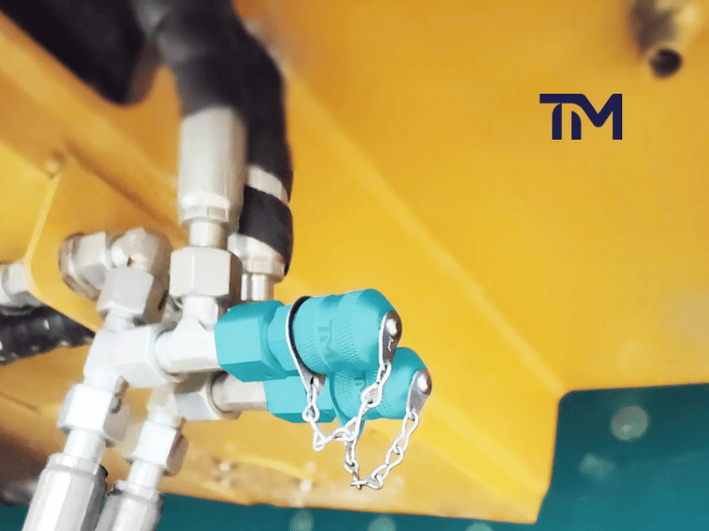
- Incoming hardware and hose are checked against the released specification before anything is cut.
- Assemblies are built to the frozen configuration from your order, with the crimp set recorded for the run.
- Every finished assembly is inspected before packing — 100% outgoing inspection, no sampling.
- Packing carries your identification scheme, which means the parts arrive under the same code your stores already use.
Fatigue testing is part of how this product line was validated, and our records say the assemblies passed. A pass is not a rating on its own: ISO 6605:2017 supplies uniform test methods for hoses and hose assemblies, while the acceptance criteria a part has to meet come from the applicable product specification. If you need a fatigue figure you can hold a supplier to, name the test and the criterion on the order and ask to be quoted against it.
Traceability Is Something You Write Into the Order
Traceability documentation has moved from a differentiator to a purchasing requirement in hydraulic connectors, and counterfeit or sub-standard aftermarket fittings are the risk driving it. What suppliers rarely say out loud is that the records only exist because somebody asked for them on the order. In ISO 9001 terms, evidence of unique identification of outputs is a retained record when traceability is a requirement — a conditional clause, not a universal one.
| What to ask for | Why it exists | What it does not prove on its own |
|---|---|---|
| A named inspection document type | ISO 10474:2013 defines the types of inspection document supplied to the purchaser according to the order requirements for steel and steel products, alongside the general technical delivery conditions. | That the values on it were produced under a chain you can audit. |
| The test method and the acceptance criterion, separately | ISO 6605:2017 supplies uniform test methods for hydraulic hoses and hose assemblies; the criteria a part must meet come from the product specification. | That a passing result under one method means a pass under the criteria you actually need. |
| A proof pressure test on the finished assembly | A hydrostatic proof test pressurises the assembly above its working pressure without taking it to burst, and it is the check most buyers mean when they say the hose was pressure tested. ISO 6605:2017 covers the method; the proof pressure and the hold time are yours to state on the order. | That a sister assembly from the same batch shares the result, unless the order asked for the test on every piece. |
| Unique identification of the output | ISO 9001 retains this evidence where traceability is a requirement, which is why it belongs in your purchase order rather than in our brochure. | Anything at all, if the requirement was never stated on the order. |
| The chain behind the certificate, not the number on it | NIST's guidance on metrological traceability states that a test report number is for administrative use and does not itself address the elements of traceability. | That the reference used was itself traceable, which is the part worth checking. |
"People ask us for the certificate number first. The number is administration — what settles the question is the chain behind it. So we ask buyers to name the documents they want in the purchase order, and we build the records against that list instead of sending a folder nobody specified."
Two things sit outside that table and are worth separating on your order. Calibration traceability and material traceability are different chains — a calibrated instrument tells you a reading is sound, not where the steel came from — so name them as two requirements rather than one. And we keep material records for every batch we build, released when your order calls for them.
From Drawing to Delivery
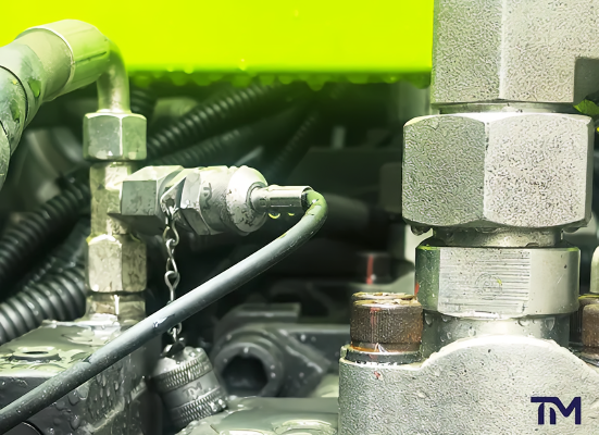
01
Send what you have: a drawing, a part number, a photo of the port, or the failed hose itself. Incomplete information is normal at this stage and does not stop the process.
02
Specification review: we identify the port, confirm which of the four stud ends ISO 15171-2 permits it maps to, and flag anything that will not seat before it becomes an order.
03
Written quotation: configuration, pressure class, quantity brackets, lead time and terms, returned within 24 hours on business days.
04
Specification freeze: the agreed configuration is recorded as the build reference, so the repeat order in eighteen months is the same part.
05
Build and inspect: if an assembly leaves here outside the frozen specification, that is ours to correct, and we remake it against the same written criteria we inspected it to.
06
Pack and ship: marked to your scheme, FOB or EX-Works as standard.
DN2 or DN4: How to Choose the Bore
DN2 is the volume size in this category and DN4 is the high-flow variant, which leaves buyers guessing at where the line falls. Honestly, bore is decisive for some jobs and irrelevant for others, and the deciding factor is what you are measuring rather than how much pressure you are measuring.
| Selection criterion | DN2 | DN4 |
|---|---|---|
| Inside diameter | 2 mm (0.079 in) | 4 mm (0.157 in) |
| Flow area | Baseline | Four times the cross-sectional area of DN2 |
| Fill and bleed time on a gauge line | Slower, and noticeably so on long runs | Faster, which shortens the wait before a reading settles |
| Dynamic measurement fidelity | Governed by bore and hose length together, not by bore alone | Governed by bore and hose length together, not by bore alone |
| Static and average pressure readings | Unaffected by bore | Unaffected by bore |
| Minimum bend radius | Tighter — routes into confined spaces more easily | Larger — needs a wider sweep at every corner |
| Routing space | The easier hose to thread through a packed bundle of lines | Wants a planned route rather than an opportunistic one |
| Off-the-shelf availability | The size most points are installed for | The high-flow variant, built to order more often than stocked |
| Unit cost | Lower | Above DN2 on the same end types |
| Where it fits | Routine gauge readings, permanent monitoring points, tight installations | Flow-based instruments, fast fill and bleed, long runs, dynamic work |
The Two-Line Selection Rule
- Reading static or average pressure only — bore is not the deciding factor. Choose on flow, routing space and cost, and DN2 is usually the better buy.
- Measuring dynamic waveforms or pressure pulsation — bore and hose length have to be controlled together, and the shortest workable length matters more than simply going up a bore size.
Working through a mixed fleet of test points?
Open the DN2 / DN4 bore selector
Where DN4 Test Hoses Run
DN4 assemblies show up wherever a pressure test has to be taken quickly, repeatedly, and without shutting the circuit down. Below are the applications we build for most often, described by what the hose is doing rather than by a customer story we are not free to tell.
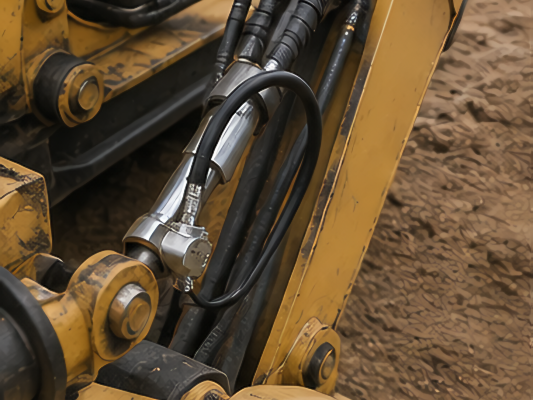
Construction and earthmoving
Excavators and loaders on relief and load-sense checks with a technician working down a list of test points using a single hose and gauge.
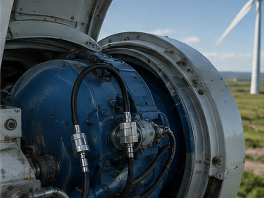
Wind power
Pitch and yaw hydraulic circuits inside the nacelle, where a single site visit costs enough on its own that a slow-filling gauge line shows up in the budget.
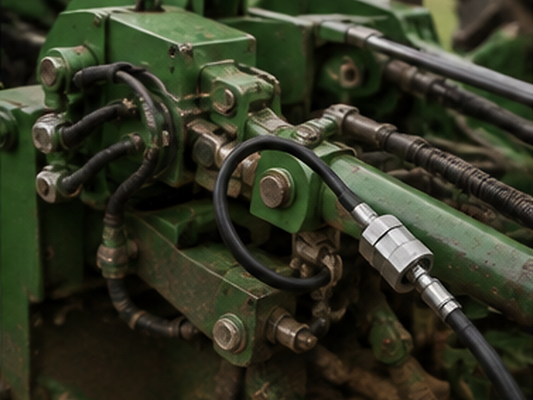
Agricultural machinery
Seasonal equipment brought back into service after storage, where the first task is confirming that pressures still match the manual.

Automated production lines
Clamping and pressing circuits with permanently installed points, so a reading can be taken between shifts without breaking a line.
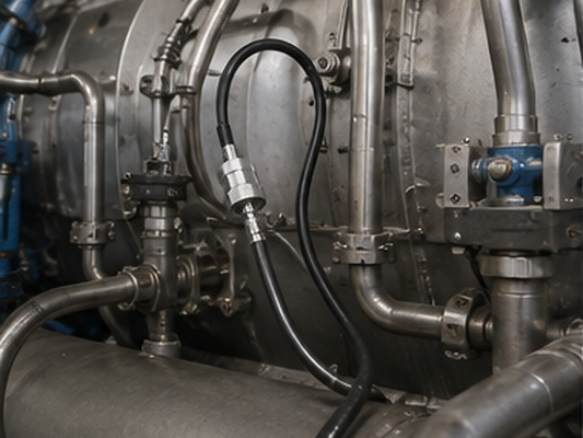
Power generation
Turbine control and governor hydraulics, where diagnostic access must be provided without creating an additional leak path into the circuit.
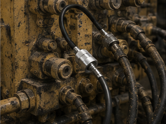
Metallurgy and mining
Heavy-duty circuits in dusty, abrasive conditions, where cover durability and corrosion protection decide how long an assembly survives.
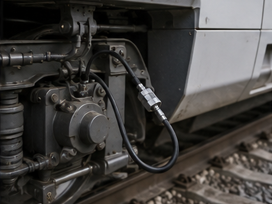
Rail transit
Braking and door hydraulics on scheduled maintenance, where the same measurement is repeated over an entire fleet.
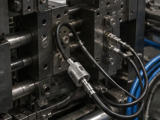
General manufacturing
Machine tools and injection equipment, where a permanent test point converts a strip-down into a two-minute check.
We supply DN4 and DN2 test hose assemblies to equipment builders and service networks including SANY, XCMG, Parker, HAWE, GE, Rexroth and Caterpillar.
When DN4 Is Not the Right Size
DN4 is not always the safe default, and specifying it across a whole machine is the mistake we correct most often on incoming drawings. The trade-off is real, because every millimetre of bore you gain costs you bend radius, routing freedom and unit price. Below are three situations where that trade goes against you.
| Situation | Why it works against you | What to do instead |
|---|---|---|
| Routing through a packed bundle of lines or a crowded manifold face | The larger bend radius fights you at every corner, and forcing the bend to make the route work is what shortens the life of the assembly. | Specify DN2 at those points and keep DN4 for the high-flow branches. Both sizes go on the same order and ship together. |
| Peak duty above the 630 bar (9,137 psi) class | Our DN4 assemblies are rated to 630 bar (9,137 psi) maximum working pressure. Running any hose past its class is not a margin question. | Move that point to a test line rated above your measured peak, and send us the peak so the quotation carries the right hardware. |
| Reading static or average pressure only | Bore is not the deciding factor for a steady reading, so the extra flow capacity does nothing for the number on the dial and still costs you at every corner. | Use DN2 there. Switch to DN4 where you need faster fill and bleed, a flow-based instrument, or dynamic waveform work. |
Working through a list of test points and unsure which size each one wants?
Send us the port list and we mark up DN2 or DN4 against each line
DN4 Hydraulic Test Hoses Engineering Tools
DN2 / DN4 Bore Selector
Calculate internal volume and fill time against your exact configuration to determine whether your circuit requires a DN2 or DN4 diagnostic assembly.
Test Point Identifier
Walk through four physical checks to definitively identify the coupling thread and matching hose end required for your existing installed test points.
Pressure Class Reader
Verify maximum working pressure and connect-under-pressure limits simultaneously to confirm the exact pressure class of any diagnostic hose datasheet.
Frequently Asked Questions
What is a hydraulic test point, and how does the hose connect to it?
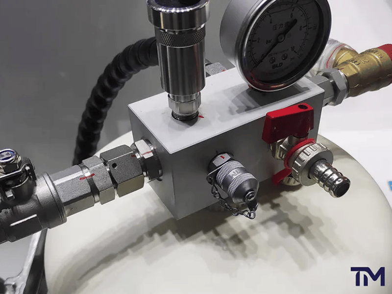
A hydraulic test point is a permanently installed coupling in the circuit that lets a gauge, transducer or data logger be connected for a pressure test without draining or opening the line. The hose carries the matching coupling half; pushing it on opens an internal poppet, and removing it closes the poppet again. ISO 15171-2 is the part of the standard covering couplings designed to be connected and disconnected while the system stays pressurised.
DN2 vs DN4: when do you actually need the larger bore?
DN4 is necessary when the flow through the line matters — filling and bleeding a gauge line faster, feeding a flow-based instrument, reducing the settling time on a long run. For static and average pressures, bore is not the deciding factor and DN2 is a simpler, less expensive hose. For dynamic waveform work, bore and length need to be managed together instead of bore being the lone lever.
Why do two hoses both labelled DN4 carry different pressure ratings?
DN4 designates a 4 mm nominal bore, not a pressure class, so assemblies at 340 bar (4,931 psi), 500 bar (7,252 psi) and 630 bar (9,137 psi) are all correctly labelled DN4. A datasheet also often carries two different pressure figures — the maximum working pressure and a lower figure for connecting while the circuit is live. Ask which number you are reading before you compare two quotations.
Are M16 × 2, Test 20 and 1620 series the same connection?
They describe the same coupling thread from three directions: M16 × 2 is the thread specification, Test 20 is the series name used in one supplier ecosystem, and 1620 is the series number used in another. The pattern to watch is M16 × 1.5, written as the 1615 series, which looks almost identical and will not seat. Half a millimetre of pitch is the most common reason a test hose arrives and cannot be fitted.
Will these hoses connect to my existing Minimess, Stauff, MCS or Minipress test points?
Our DN4 assemblies are built to mate with Minimess, Stauff, MCS and Minipress test points already installed in your machines. What settles it is the coupling thread on the point itself, then the cap type, then the stud end going into the machine port. Send a photo of the point with your enquiry and we confirm the fit before you place the order.
Which fluids and temperature ranges are these hoses rated for?
Mineral-oil hydraulic systems are the default scope, which is the same default ISO 15171-2 works from — that standard states that use of the coupling with fluids other than mineral oil requires an agreement between the supplier and the purchaser. For HFC, HFD, water-glycol, phosphate ester or any other fluid, we confirm the build by agreement rather than publishing a blanket compatibility list. We set the temperature band the same way, against the configuration you order.
Can I order a hose with the pressure gauge already fitted?
Yes — the gauge-fitted assembly is one of the six end configurations we build, supplied with the gauge mounted and leak-checked as a single unit. Tell us the pressure range you want on the dial, whether the gauge is bottom-entry or back-entry, and whether you need a swivel at the gauge end. It ships as one part number, which is what makes it useful for field kits.
What is the minimum order quantity, and do you provide samples?
There is no fixed minimum for standard test hose builds, and single pieces are accepted; custom lengths, fittings and gauge combinations are quoted per drawing with volume-based pricing. Samples are provided at no charge for standard configurations, and the requester covers the international courier freight. Production orders run on 30% deposit by T/T with the 70% balance settled before shipment.
How long does production take, and how fast is a quote?
Quotes are returned within 24 hours on business days, reviewed by an engineer rather than produced from a price table. Production runs 4–6 weeks after specification confirmation, which is about 20 to 30 business days, and the date is confirmed and locked with the quotation. Lead time starts at specification confirmation and excludes transit.
Can you supply hoses with our own branding?
We apply OEM marking to your part number on the ferrule or on a fitted tag, and pack to your scheme so the parts arrive under the code your stores already use. If you want a recognised coding system rather than your own, SAE J846 defines one for fluid conductors and connectors — and the standard is explicit that it does not supersede an identification system you already run. Send the marking format with your drawing and it goes into the frozen specification.
