
Get in touch with TIME Company


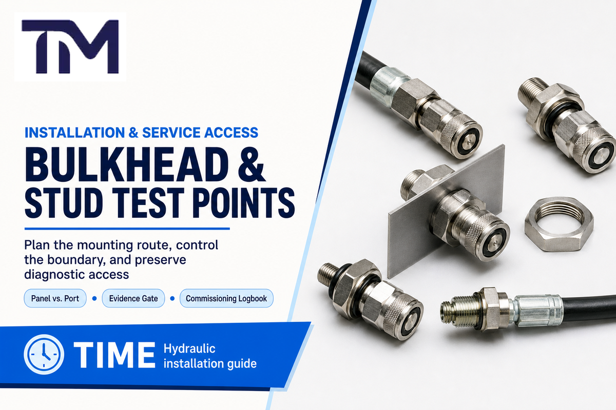
Bulkhead & Stud Test Points are diagnostic connections that create a controlled place to connect measuring equipment, but they take different mounting paths. A bulkhead point carries the service interface through a panel or enclosure. A stud point terminates directly at a documented hydraulic port. That difference changes what must be measured, restrained, sealed, inspected, and recorded.
This guide is for maintenance technicians, service engineers, and technical buyers who already know that a test point is needed but still have to make the installation reviewable. It doesn’t select a model or publish a universal torque, clearance, pressure, or inspection interval. Those decisions remain tied to the exact machine procedure, component drawing, fluid, seal, and authorized pressure state.
Safety boundary
Installing, tightening, repairing, or replacing a permanent hydraulic test point is servicing work. Follow the site’s energy-control procedure, isolate the system, control stored and reaccumulating energy, and verify the required state before work begins. Connecting a designated measuring coupling within its documented limits is a different activity; it doesn’t authorize work on the permanent fitting while pressurized.
Bulkhead vs. Stud Test Points: Two Mounting Paths
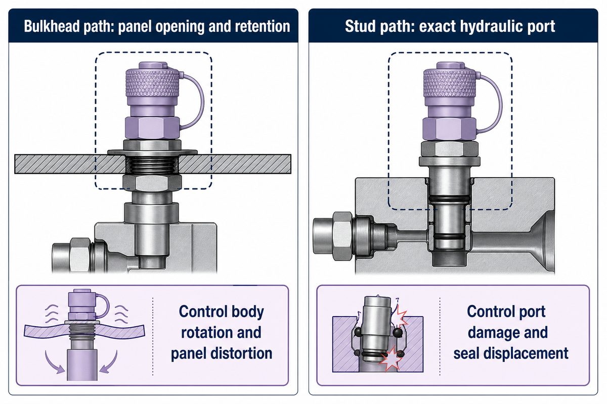
With a bulkhead test point, the body passes through a prepared panel opening and is retained by the product’s documented locking arrangement. By contrast, a stud test point screws into a defined machine-side port. Both may present a familiar diagnostic connection to the technician, but that familiar service end doesn’t prove that their mounting ends, seals, pressure permissions, or installation instructions are interchangeable.
| Evidence field | Bulkhead path | Stud path |
|---|---|---|
| Mounting boundary | Panel opening, permitted panel range, retention, and orientation | Exact hydraulic port definition and engagement |
| Primary seal evidence | Product drawing for each connected side and any panel-related seal | Documented port form, seal location, and seal condition |
| Load to control | Body rotation, panel distortion, lock movement, and attached-line load | Port damage, seal displacement, body orientation, and adjacent-component load |
| Access proof | Approach, coupling, observation, cap, and hose-routing space at the panel | Reach and visibility at the machine port, including room for the mating connector |
Classify the mounting route before opening a model table. If the interface must be moved through a guard or console for repeat service, the review begins with the panel and the service envelope. If the point will remain at the machine port, the review begins with the port drawing and sealing boundary.
Plan the 3-Sided Service Access Envelope Before Cutting or Tapping
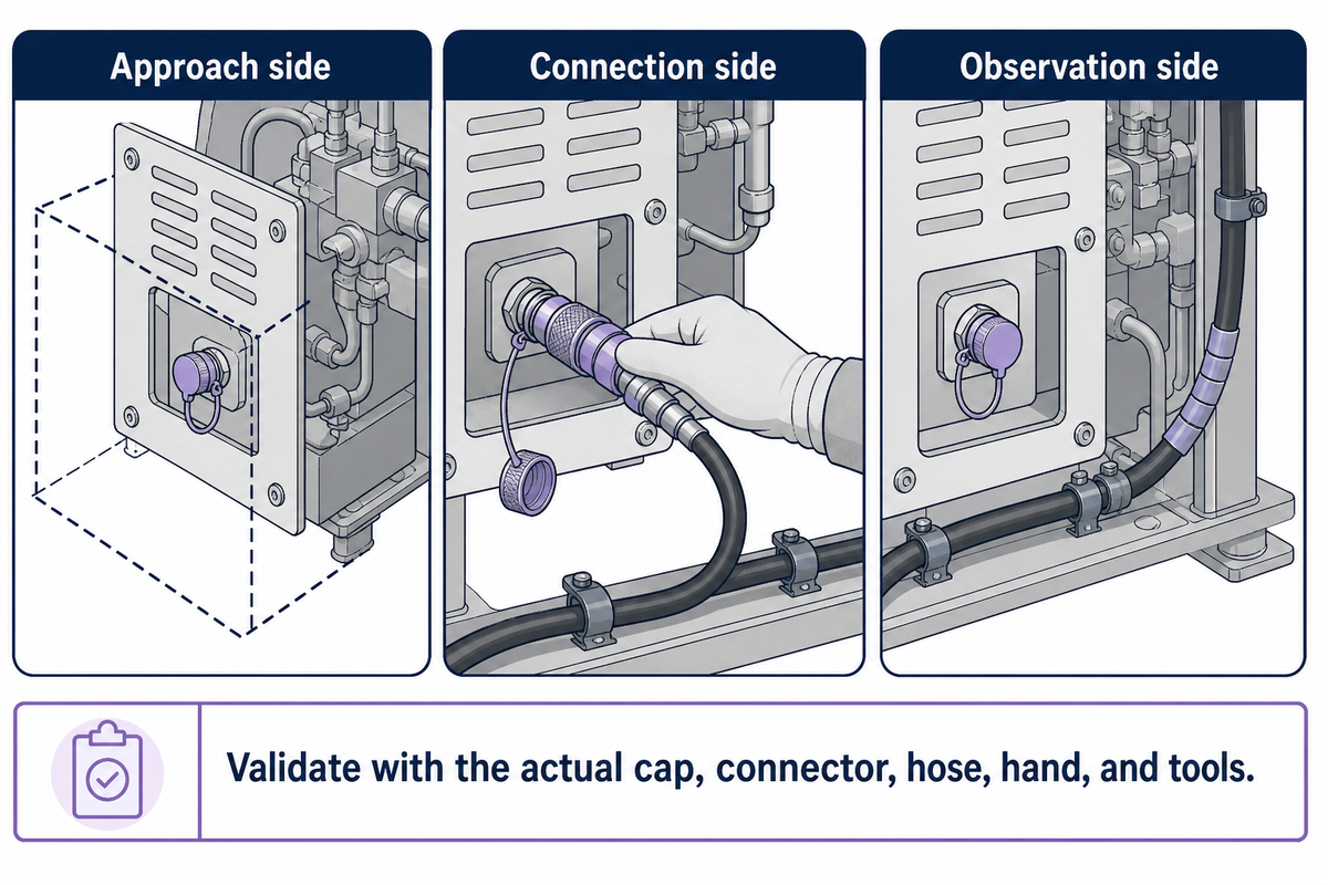
On a two-dimensional drawing, a point may look reachable and still be awkward or unsafe to use on the machine. The cap might hit a guard, the mating connector may only approach at an angle, or the hose may be forced against an edge. The technician could connect the gauge yet have no clear view of contamination, movement, or leakage around the installed boundary.
The 3-Sided Service Access Envelope is an editorial planning tool for those conflicts. It isn’t a standard-defined safety zone and it doesn’t create a universal clearance. Validate it against the exact cap, mating connector, test hose, hand position, required tools, panel geometry, and machine instructions.
The three task spaces
- Approach side: Can the technician identify the point, see the cap, clean the exterior, and reach it without contacting hot, moving, or sharp nearby parts?
- Connection side: Is there room to remove and retain the cap, align the exact mating connector, complete the documented coupling action, and route the hose without side-loading the interface?
- Observation side: Can the installed boundary, lock, surrounding surface, and hose route be observed for movement, contamination, or leakage before and during the authorized check?
In 2023, a Fluid Power Journal article by Robert Mackey, general manager of MAIN Manufacturing Products, described interference-free space around a gauge port and gave a 75 mm (3 in) diameter by 200 mm (8 in) high envelope. Because it is a manufacturer-authored example, treat it only as an illustration of the spatial question, not as a current product specification or independent research. The actual required space may be larger, smaller, or differently shaped and must come from current component and machine evidence. One field discussion, in which a user had no access to the hydraulic ports, illustrates the practical consequence: an inaccessible measurement location may exist on the circuit diagram but fail as a maintainable service route.
Where should a panel-mounted hydraulic test point be located?
Locate it where the machine documentation permits the intended measurement and where the full service task can be completed without forcing the connector or hose. Prefer a position that remains visible, cleanable, identifiable, and protected after guards, doors, labels, wiring, and nearby hoses are installed. Confirm that the panel can accept the documented mounting arrangement.
Then verify the position on the actual machine, not only the drawing, using the cap, mating connector, hose, hand, and any required tool. Check that the connected line won’t carry panel movement or vibration into another joint. Convenience alone doesn’t prove that a remote point answers the same diagnostic question as the machine manual’s specified port.
For the mating diagnostic path, the hydraulic test hoses and fittings guide separates hose and connector selection from the permanent mounting decision.
Terminology note for service records
Use the exact term printed on the drawing. An adapter or adaptor, valve, check valve, vent, cylinder-venting point, accessory, and diagnostic access point are not automatic synonyms. Likewise, DN4 should be recorded only when the current supplier document actually uses DN4 for that hydraulic component or passage.
State the task as pressure monitoring, hydraulic pressure testing, preventative maintenance, or observation of system operation only when the procedure supports that purpose. Maintenance personnel should not turn words such as precision, reliability, durability, or accurate pressure into performance claims without evidence for the complete measuring chain. An EN ISO reference also needs its exact number and applicable product scope.
Stop at the Pre-Installation Evidence Gate
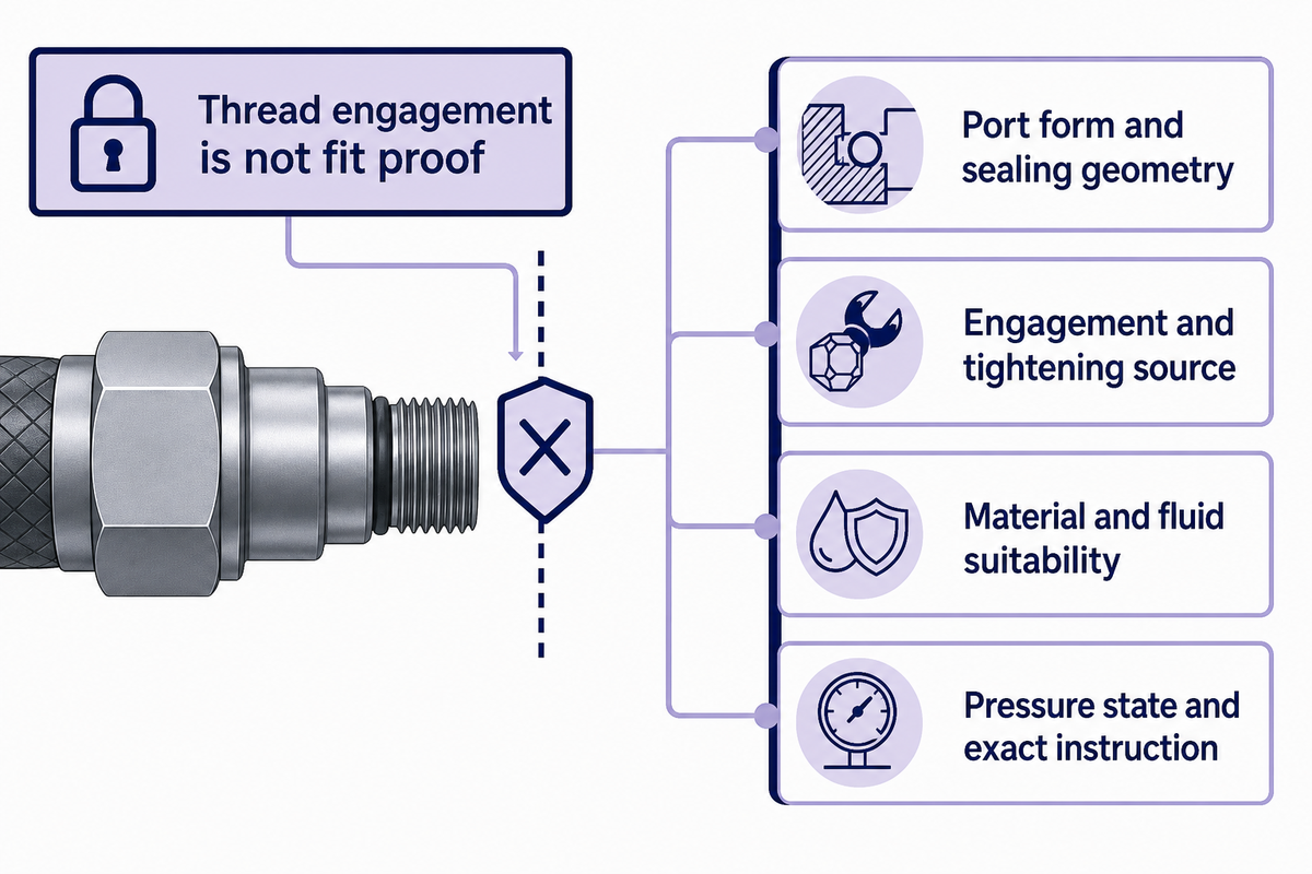
Thread engagement isn’t a completed fit decision. By itself, it doesn’t establish the port form, sealing geometry, permitted engagement, torque, material and fluid suitability, pressure state, or cross-brand compatibility. Whether the test point fitting has a carbon-steel or stainless steel body doesn’t resolve those separate questions, and the same evidence gate applies whether the machine carries a Stauff test point, a Minimess test point, Hydac test points, or a Hydrotechnik test point, since a familiar coupling profile from one manufacturer’s line is not proof of another’s port or seal geometry. The evidence gate prevents a familiar-looking connection from becoming an undocumented installation.
| Evidence type | Acceptable evidence | Stop condition |
|---|---|---|
| Mounting route | Current product drawing and machine location | Panel and port paths are being treated as equivalent |
| Machine-side interface | Exact port or panel definition | Only nominal thread or a catalogue photograph is known |
| Seal | Seal type, location, material, and replacement rule | Sealant or an O-ring is being added by assumption |
| Tightening | Exact manufacturer instruction and identified interface | A generic torque chart is the only source |
| Pressure permission | Machine procedure and exact component limits | A standard number or another series’ rating is being borrowed |
| Fluid and temperature | Documented compatibility for the actual fluid and range | Compatibility is inferred from body material alone |
| Energy control | Site procedure, isolation points, verification, and reaccumulation controls | Pump stopped or one relief action is being treated as proof of zero energy |
| Component identity | Exact part identifier, revision, marking, and current drawing | A visually similar component is being substituted |
| Service envelope | Actual cap, mating connector, hose, hand/tool, and observation task spaces | Only a nominal panel location has been reviewed |
Keep unknown fields marked unknown. Don’t replace them with a value from a visually similar product. Use the thread reference to document the machine-side port and seal boundary, but the current machine and component documents still control approval.
Install a Bulkhead Test Point Without Losing Orientation or Access
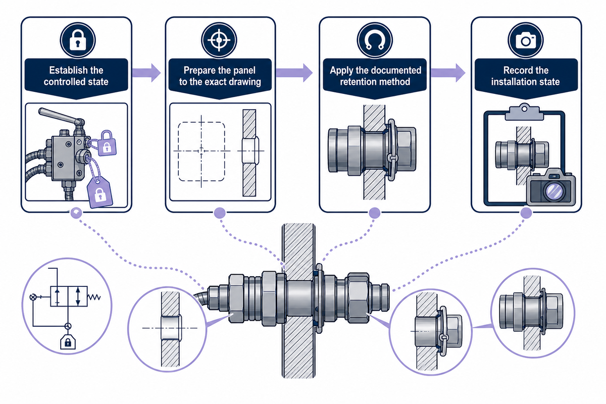
The order matters. With the pre-installation evidence gate cleared for the bulkhead route, each step protects the panel, body, retention arrangement, connected line, and service envelope without filling evidence gaps with an invented torque or panel-thickness value.
- Establish the controlled state. Use the site’s energy-control procedure. Isolate sources, control stored and reaccumulating energy, and verify the required state before opening the system or changing the permanent fitting.
- Confirm the released location. Match the machine drawing, measurement purpose, panel position, and component revision. Recheck the three service task spaces with the actual mating parts.
- Prepare the panel to the exact drawing. Use the specified opening and permitted panel condition. Remove burrs and loose debris without changing an edge, surface, or finish that the product drawing relies on.
- Protect the hydraulic boundary. Use the site’s contamination-control practice. A surface that looks clean isn’t proof of a measured particle-cleanliness class.
- Orient and support the body. Position the point so the cap, connector, and hose route remain usable. Support connected plumbing as instructed; don’t use the bulkhead body to pull a misaligned line into place.
- Apply the documented retention method. Control body rotation and tighten only the identified interface with the product-specific instruction. Don’t transfer wrench load into the connected line or another seal.
- Recheck the installed geometry. Confirm that the lock is seated as documented, the panel isn’t distorted, markings remain visible, and the cap and mating connector can be operated without interference.
- Record the installation state. Photograph the final orientation and record drawing revision, component identity, seal evidence, tightening source, and technician/date before commissioning.
If the drawing doesn’t identify how the body is restrained or which interface receives the tightening action, stop. “Hold the nearest hex” isn’t a universal instruction. The correct reaction point depends on the product construction and connected assembly.
Install a Stud Test Point at the Documented Port Boundary
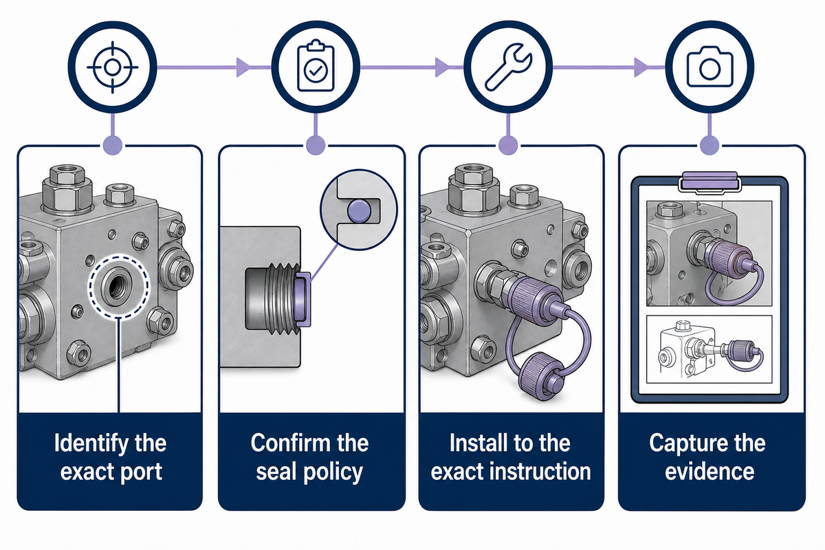
The stud path removes the panel opening and locknut from the review, but puts the machine port at the center of it. Unlike the bulkhead sequence above, there is no panel or locking arrangement to restrain here. Preparation must follow the documented port and seal, not whatever the external thread appears to be.
- Control energy and access. Apply the same isolation, stored-energy, reaccumulation, and verification requirements used for any permanent hydraulic connection work.
- Identify the exact port. Confirm function, location, port standard or drawing, thread, sealing form, permitted engagement, and surrounding component material. Don’t assume that a convenient port measures the same condition as the specified one.
- Confirm the seal policy. Determine whether the boundary uses an O-ring, bonded seal, formed seat, taper thread, or another documented arrangement. Install only the specified seal in the specified location.
- Inspect without altering the boundary. Check threads, sealing face, and surrounding surface for damage or contamination. Escalate defects rather than dressing, tapping, or adding sealant unless the controlling repair instruction explicitly allows it.
- Install to the exact instruction. Start the stud without cross-threading, keep the body aligned, and use the product-specific tightening source. Generic torque can damage the port or change seal compression.
- Verify orientation and access. Confirm that the installed point remains identifiable, capped, cleanable, connectable, observable, and protected from unintended side load.
- Capture the evidence. Record the port definition, seal identity, instruction revision, final orientation, and any unresolved observation before controlled commissioning.
Fluid compatibility belongs in this decision. The public scope for ISO 15171-2 describes a diagnostic coupling family designed for mineral-oil hydraulic systems and says other fluids require agreement between supplier and purchaser. That statement is a scope boundary, not a compatibility approval for a particular TIME Hydraulic part.
Commission With the Clean-Connect-Confirm Logbook
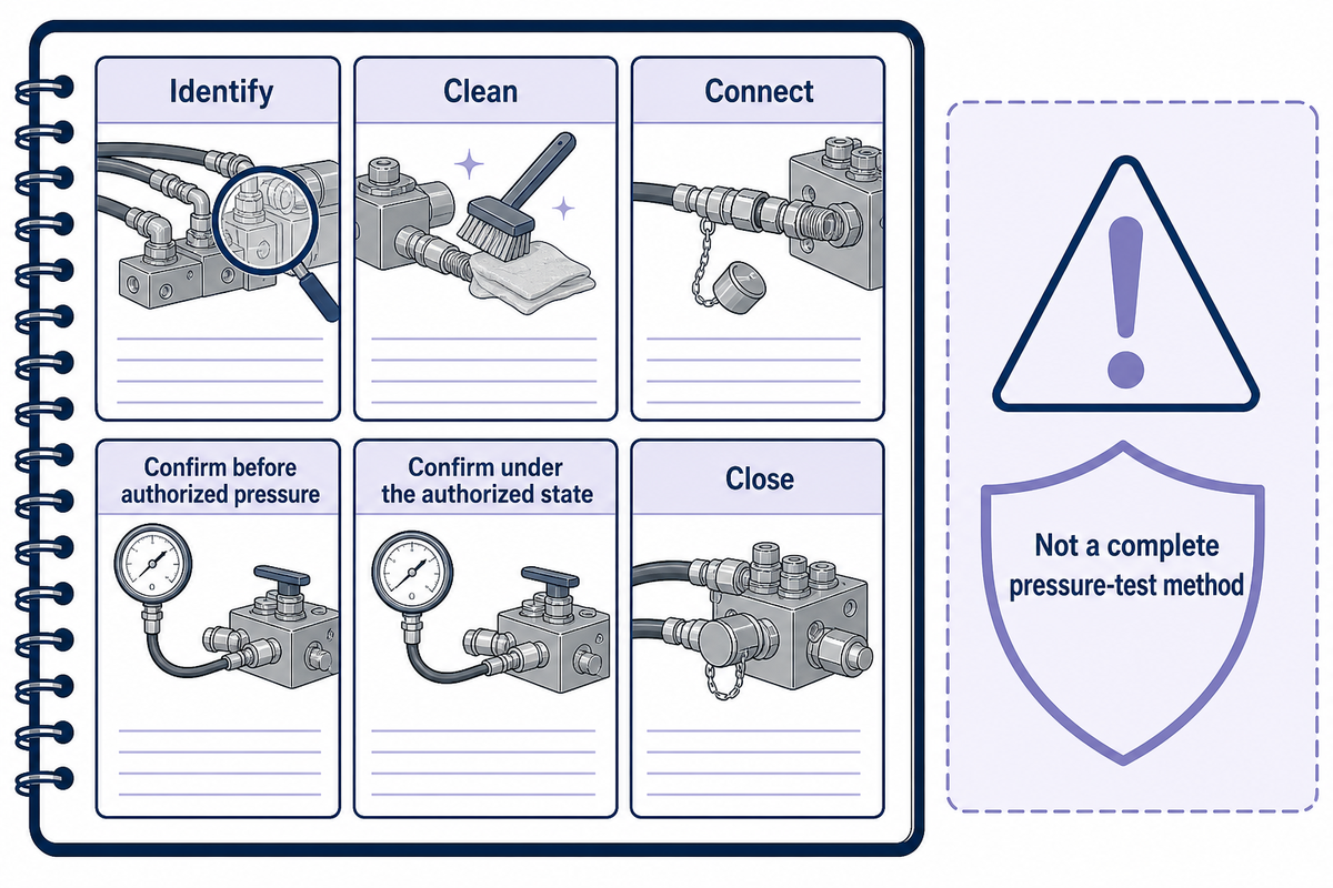
The Clean-Connect-Confirm Logbook makes the installed state reviewable. Once either the bulkhead or the stud path above is installed and its evidence captured, this logbook is what carries that installation into commissioning. It isn’t a complete pressure-test method. UK HSE GS4 is cited here as regulator guidance for the safety-control categories, not as United States law or a machine-specific procedure. If the organization’s written procedure calls for pressure testing after connector work, follow the applicable law, site requirements, and controlled plan for safe energization, monitoring, evacuation, overpressure prevention, operator exposure, segregation, and connector condition. Don’t improvise a test from this article.
Clean-Connect-Confirm Logbook fields
- Identify: machine, circuit location, mounting route, component identifier, drawing/instruction revision, seal record, installer, and date.
- Clean: exterior visibly cleaned, cap handling controlled, mating connector managed under the site’s contamination procedure, and no cleanliness class claimed without the required measurement. This is a conservative documentation rule in this guide, not a claim that a visual check implements a cleanliness standard.
- Connect: exact approved mating connector and hose identified; coupling action, hose route, restraint, and observation location confirmed under the controlling procedure.
- Confirm before authorized pressure: retention, orientation, cap condition, panel or port surface, connected-line support, access, and unresolved defects recorded.
- Confirm under the authorized state: record only observations permitted by the written test or operating procedure, using remote observation where that procedure requires it. Never search for a pressurized leak by hand.
- Close: controlled disconnection, cap replacement, post-use exterior condition, abnormal movement or leakage, disposition owner, and return-to-service approval.
A dry exterior before energization doesn’t prove that the boundary will remain acceptable under the authorized state. At the same time, standing close enough to inspect a pressurized connection creates exposure. HSE pressure-testing guidance favors reducing operator presence and using remote methods where practicable. The commissioning record should name the governing procedure and observation method instead of simply telling a technician to “watch closely.”
The reason a leak is never searched for by hand is documented, not theoretical. A 2014 UK Health and Safety Executive safety alert (FOD 4-2014) on hydraulic injection injury records that anecdotal evidence places the injury threshold as low as 7 bar (101.5 psi), while serious reported instances have occurred at pressures over 100 bar (1450 psi). The same alert states that without prompt medical treatment, a victim may experience intense throbbing pain within 4 to 6 hours, and untreated injection injuries can lead to amputation of the affected part.
| Reported figure | Pressure / time | What it means for this guide |
|---|---|---|
| Anecdotal minimum injury pressure | 7 bar (101.5 psi) | Even a fitting that looks like a low-pressure test point can inject fluid through skin |
| Documented serious cases | Over 100 bar (1450 psi) | This is well within the range of the ISO 15171-2 connection and working-pressure values discussed below |
| Reported symptom escalation window | 4 to 6 hours | Supports treating any suspected injection injury as an immediate medical emergency, not a wait-and-see wound |
Inspect the Interface and Preserve Service Access
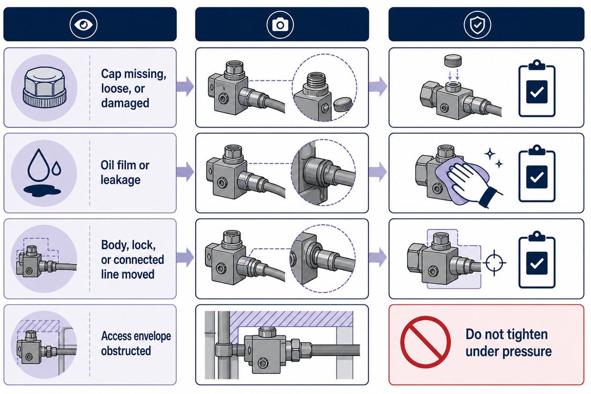
There’s no defensible universal inspection interval for all bulkhead and stud test points. The commissioning logbook above records the installed baseline; inspection is what confirms that baseline still holds. Use the machine maintenance plan and exact component instructions. Also trigger review after relevant service work, impact, cap loss, contamination, corrosion, unexpected movement, leakage, or nearby modification.
| Observation | Evidence to capture | Controlled response |
|---|---|---|
| Cap missing, loose, or damaged | Condition, contamination exposure, retention feature | Protect the point and follow the component procedure before reuse |
| Oil film or leakage | Exact location, machine state, recurrence, nearby joints | Do not tighten under pressure; isolate and escalate under the repair procedure |
| Body, lock, or connected line moved | Before/after orientation, panel condition, support, recent work | Remove from service decision-making until the mounting boundary is reviewed |
| Corrosion, damaged thread, or sealing-face defect | Location, depth/extent if the procedure defines it, fluid/environment | Use the manufacturer’s acceptance or replacement criteria |
| Access envelope obstructed | New guard, hose, cable, label, or panel change | Restore a validated task space or complete an engineered relocation review |
| Identity or instruction unknown | Marking, photographs, machine record, document search | Keep status unknown; do not substitute an apparent equivalent |
How can contamination be avoided when using a hydraulic test point?
Start with the site’s contamination-control procedure. Clean the exterior before removing the cap, keep the cap in a controlled place, and inspect the mating connector before connection. Prevent dirty gloves, loose fibers, damaged caps, or exposed hose ends from contacting the interface. Connect and disconnect without dragging the hose across contaminated surfaces.
Afterward, inspect the point, replace the cap as documented, and record unexpected debris, sealing-surface damage, or unusual fluid appearance. “Looks clean” is only a visual observation; it isn’t a sampled particle-cleanliness result. If the application requires a measured target, use the specified sampling and measurement method rather than inferring it from the connector’s appearance.
Keep ISO 15171-2 at the Installation Handoff
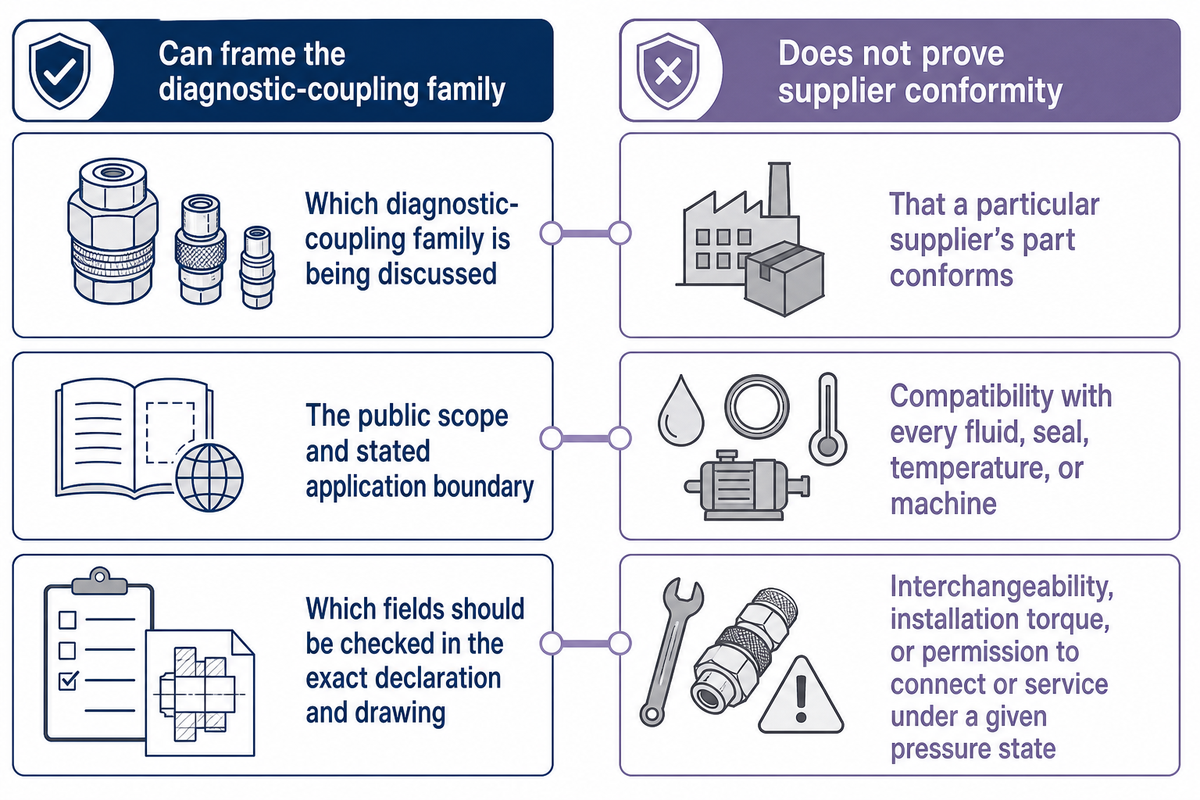
ISO 15171-2 can identify the scope of a specified diagnostic-coupling family, but this installation guide stops there. The standard does not approve a mounting location, verify a supplier’s part, authorize work on a pressurized permanent fitting, choose the gauge and hose, or provide a universal tightening value. If the component data uses M16x2 (a 16 mm nominal thread diameter with a 2 mm pitch), pressure gauge connection, test coupling, pressure test point, system pressure, or published 400 bar (approximately 5,800 psi) or 630 bar (approximately 9,140 psi) scope language, carry the exact term to the compatibility review rather than converting it into installation permission here. Record the exact edition and component evidence, then separate connection-state scope from installation approval in the dedicated compatibility guide.
| Published concept | ISO catalogue scope value | What it does not establish |
|---|---|---|
| Connection under pressure | Maximum 40 MPa (400 bar / approximately 5,800 psi) for the specified M16x2 connection condition | Permission to install, tighten, repair, or replace the permanent point under pressure |
| Maximum working pressure | Up to 63 MPa (630 bar / approximately 9,140 psi), dependent on material, design, working conditions, and application | The rating of any unverified product, assembled diagnostic chain, or machine installation |
| One placement example | 75 mm (3 in) diameter by 200 mm (8 in) high interference-free space in a trade-journal example | A universal service clearance, guard distance, or safety geometry |
| A current standard reference can help establish | It does not establish by itself |
|---|---|
| Which diagnostic-coupling family is being discussed | That a particular supplier’s part conforms |
| The public scope and stated application boundary | Compatibility with every fluid, seal, temperature, or machine |
| Which fields should be checked in the exact declaration and drawing | Interchangeability, installation torque, or permission to connect or service under a given pressure state |
Pressure concepts must stay separate. A condition under which a designated diagnostic coupling may be connected is not the same as the assembly’s maximum working-pressure rating or the system pressure expected at the measurement location. Neither figure should be copied from a standard scope page and presented as a TIME Hydraulic product rating. A pressure gauge connection also has to remain within the exact gauge, hose, connector, and procedure limits. Both ISO connection-pressure figures above sit far above the 7 bar (101.5 psi) anecdotal injection-injury threshold and the over 100 bar (1450 psi) documented range covered earlier, which is exactly why every permanent fitting is treated as potentially hazardous regardless of its nominal test-point pressure.
Use the Mount-Access-Verify Readiness Board Before Model Review
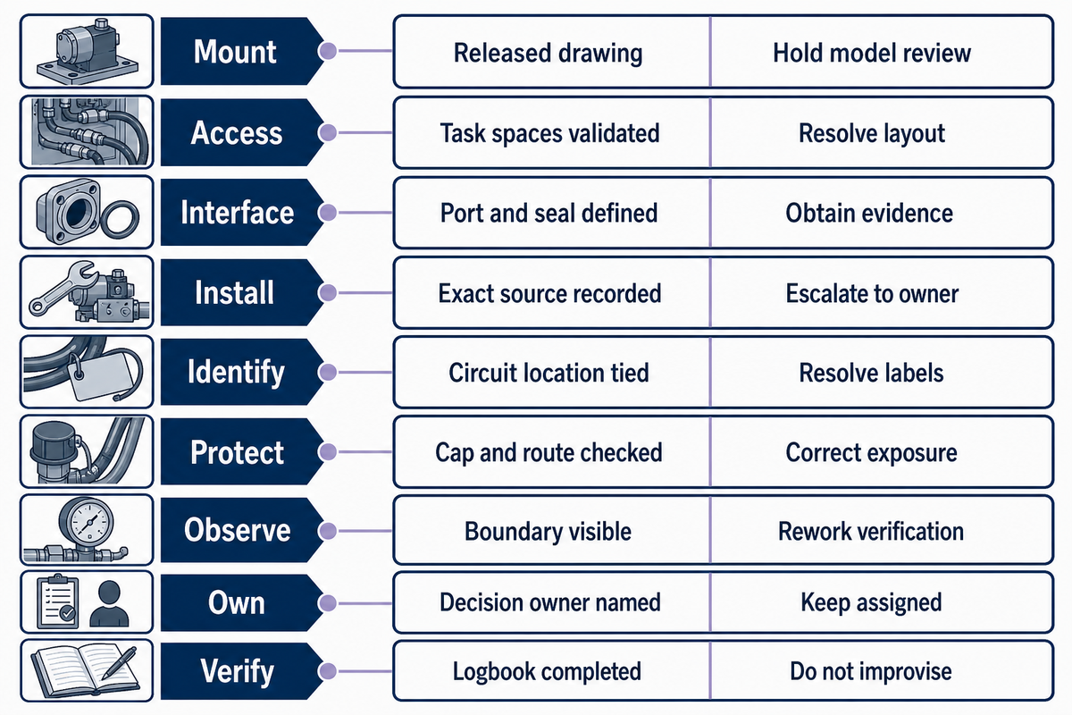
The review is ready to hand off only when someone else can see what will be mounted, where it will be reached, which machine-side boundary it uses, and how the installation will be verified. That last boundary carries forward the ISO 15171-2 scope discipline from the previous section: the standard identifies a family, it does not close out the review. The Mount-Access-Verify Readiness Board keeps those inputs together.
| Decision | Release evidence | If incomplete |
|---|---|---|
| Mount | Bulkhead or stud route; released panel/port; component drawing | Keep model review on hold |
| Access | Validated approach, connection, observation, cap, and hose task spaces | Resolve the physical layout first |
| Interface | Port/panel definition, seal, fluid, temperature, pressure-state authority | Obtain current machine and component evidence |
| Install | Isolation procedure, preparation, restraint, and exact tightening source | Escalate to the procedure owner or qualified engineering review |
| Identify | Durable point identification tied to the approved circuit location | Resolve ambiguous labels before service release |
| Protect | Cap retention, impact protection, hose route, and contamination controls | Correct the exposure or access route |
| Observe | Visible boundary, movement, leakage, and surrounding interference | Rework the location or verification plan |
| Own | Named decision owner for unresolved installation or return-to-service questions | Keep the decision open and assigned |
| Verify | Written commissioning/test authority and completed Clean-Connect-Confirm Logbook fields | Do not improvise a pressure test or return-to-service decision |
After these fields are documented, procurement can compare exact configurations through the bulkhead and stud test-point solutions page. That page owns model, material, seal, configuration, fit-review, pricing, and quotation intent; this guide intentionally doesn’t reproduce those commercial tables. For a broader route across test-point types, use the hydraulic test-point selection guide.
Frequently Asked Questions
What is the practical difference between a bulkhead and a stud test point?
A bulkhead test point creates a service interface through a panel or enclosure boundary; a stud test point installs directly into a documented hydraulic port. The bulkhead path therefore adds panel, retention, orientation, and service-envelope evidence. The stud path centers on exact port and seal identification. Neither mounting style alone establishes pressure permission or interchangeability.
Does a matching thread prove that a stud test point fits the hydraulic port?
No. The port form, sealing geometry, engagement, fluid and material suitability, tightening source, pressure limits, and manufacturer instructions still have to agree through the authorized machine operating envelope. That remains true even when the thread starts smoothly and the body looks similar. Use the port drawing, exact component data, and seal instructions as one evidence set. If a required field is unknown, record it as unknown and stop the installation decision instead of substituting a familiar part or generic value.
How much clearance should be left around a bulkhead test point?
No universal clearance applies. Required space depends on the cap, connector, hose route, hand and tool access, guards, and room to observe movement or leakage. Validate approach, connection, and observation spaces on the actual panel with mating hardware before release.
How often should hydraulic test points be inspected?
Follow the machine maintenance plan and component instructions, including any scheduled preventative maintenance. Also inspect after relevant service events, nearby modifications, cap loss, impact, contamination, corrosion, movement, or leakage. Record what triggered the inspection, the machine state, cap condition, mounting movement, contamination, and disposition. A calendar interval copied from another machine or component family is not approval for this installation. The controlling site procedure retains authority for intervals, acceptance criteria, replacement, and return to service.
Can a test point be installed or tightened while the system is pressurized?
Permanent-point installation, tightening, repair, and replacement require the controlled state defined by the site’s energy-control procedure. A product family may permit a designated measuring connector to be coupled under documented conditions, but that is a different action and does not authorize work on the installed fitting.
When should a reader move to product-level review?
Move to model review after documenting the mounting route, machine-side interface, service envelope, fluid and pressure-state boundaries, installation instruction, and verification plan. If any input is incomplete, obtain the current drawing or procedure and name the decision owner before purchasing. Do not use this guide to choose a model, material, seal, or price. Commercial decisions begin only after the installation evidence is complete and belong on the linked solution page, where the configuration can be reviewed without duplicating product content.
Sources
References & Sources
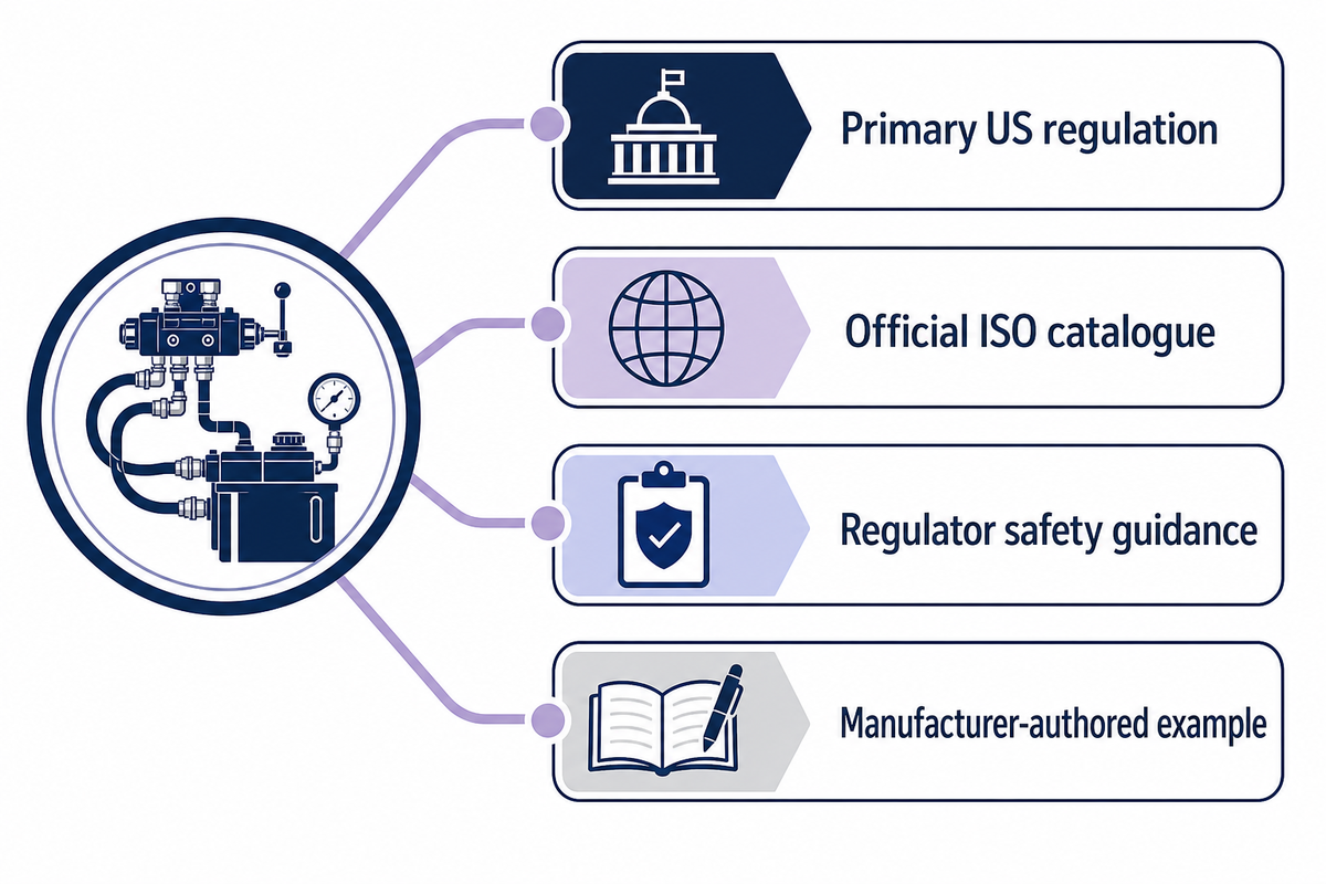
- 29 CFR 1910.147: The control of hazardous energy primary United States regulatory text for energy-control, stored-energy, and reaccumulation requirements.
- ISO 15171-2:2016 official catalogue entry diagnostic-coupling scope and current lifecycle.
- OSHA: Control of Hazardous Energy supplemental agency overview of the servicing boundary.
- HSE GS4: Safety requirements for pressure testing written safe-system, segregation, monitoring, and connector controls.
- HSE hydraulic injection injury alert pressurized-fluid injury boundary.
- Fluid Power Journal: Gauge Ports Make Life Easier placement and interference-free access example.
