
Get in touch with TIME Company

Stainless Steel Hydraulic Test Points: A Practical Selection and Verification Guide

Engineering and purchasing support for industrial hydraulic maintenance, quality, and sourcing teams.
Stainless steel test points are hydraulic diagnostic access connections selected as part of a complete hydraulic diagnostic chain. The body grade is important, but so are the external environment, machine-side port, sealing technique, hydraulic fluid, diagnostic interface, hose, instrument, pressure state, and evidence tied to the delivered lot. If any of those fields is unknown, a stainless label does not close the decision.
This guidance explains how to frame that decision without turning it into a product catalog. It supports the wider hydraulic test point family and the current commercial stainless solution page, while leaving model tables, factory capability, pricing, and quotation content out of the article.
What a Stainless Steel Hydraulic Test Point Is, and Is Not
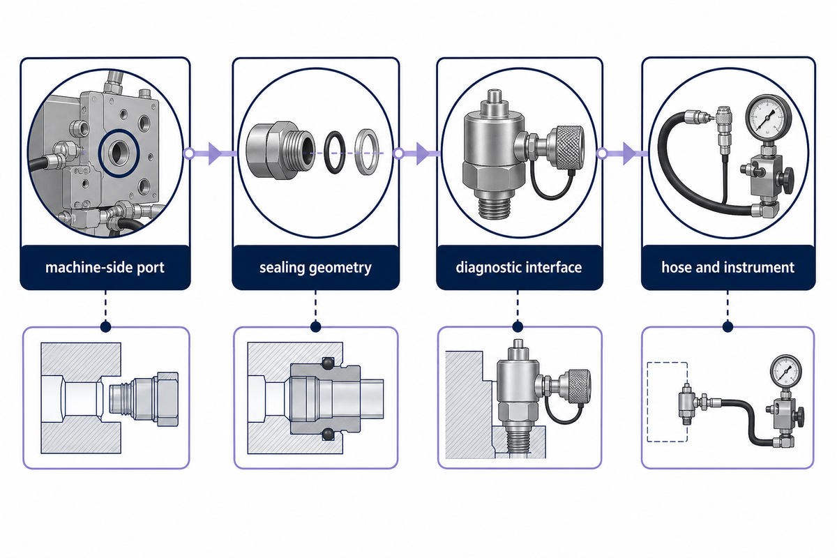
A hydraulic test point is a small diagnostic access connection. It allows an approved mating hose or adapter to connect a pressure gauge, sensor, or other measuring device to a hydraulic circuit under defined conditions. Stainless construction can improve corrosion resistance where humidity, cleaning agents, salt, or aggressive process environs make plated carbon steel a poor fit.
That statement has limitations. A stainless body isn’t a complete corrosion guarantee. It doesn’t specify the elastomer, machine-side thread, sealing geometry, diagnostic interface, mating-port metal, allowed fluid, temperature range, working pressure, or connection-under-pressure permission. It doesn’t guarantee that a certificate belongs to the parts in front of you.
Key takeaway
Choose a stainless hydraulic test point by exposure, interface, seal, pressure state, fluid, and evidence. The grade name is one field in the decision, not the decision itself.
If the near-term issue is general point selection rather than stainless alloy, start with the eight-check hydraulic test point selection guide. It keeps the two search tasks separate: this article goes deeper on stainless exposure and evidence; the selection guide covers the wider industry product-family route.
Start With Exposure, Not the Grade Label
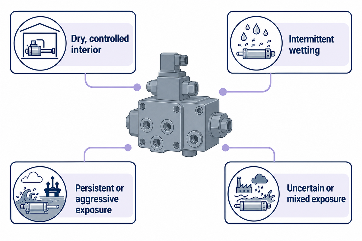
The most useful initial question isn’t “304 or 316?” It’s “What will touch, wet, heat, contaminate, or remain trapped around this connection?” A test point may carry mineral oil internally while its outer surfaces experience washdown water, salt spray, fertilizer dust, food-cleaning chemicals, condensation, or metal fines. Internal and external exposures may require different checks.
Nickel Institute guidance describes why this is important. Molybdenum gives 316 a useful directional advantage over 304 in many chloride-bearing and reducing-acid circumstances, but the same guidance keeps material choice tied to the specific service environment, cleaning agents, chloride content, and temperature. In other words, exposure-first selection doesn’t make grade irrelevant. It prevents a relative advantage from becoming an unconditional guarantee.
Stainless Exposure Review Triggers
Consult this decision tree to develop an accurate exposure record and determine how much material evidence and application review the request requires. It’s a screening tool, not a prediction of corrosion life.
| Exposure level | Facts to record | Typical decision response | What remains unproven |
|---|---|---|---|
| Controlled indoor | Dry location, stable temperature, no routine washdown, known hydraulic fluid. | Confirm whether stainless is necessary or whether a documented plated-steel option is suitable; ensure fluid and seal evidence is still closed. | Fluid/seal compatibility and exact interfaces. |
| Intermittent wetting | Condensation, occasional rinse, drying time, water chemistry, protective cap condition. | Review grade, surface condition, crevices, drainage, and maintenance frequency. | Long-term behavior at trapped-water locations. |
| Chloride or salt exposure | Source of salt, deposition, concentration pattern, temperature, wet/dry cycling, cleaning method. | Treat 316-family material as a directional improvement, then verify whether the real exposure remains within the proposed material and design envelope. | Service life; no universal chloride number closes it. |
| Aggressive cleaning or process chemicals | Chemical name, concentration, contact time, temperature, rinse, residue, frequency. | Obtain application-specific body, seal, and surface-treatment compatibility evidence. | Compatibility cannot be transferred from water or mineral oil. |
| Marine splash or road salt | Salt source, splash direction, drying, drainage, deposits, crevices, and mating-metal condition. | Review the complete exposed assembly, not only the nominal body grade. | Resistance to trapped brine or galvanic interaction. |
| Hygienic washdown | Cleaner and sanitizer identity, concentration, contact temperature, rinse quality, residue, and frequency. | Verify the body, valve, seal, cap, and surface-treatment scope against the real cleaning cycle. | Suitability transferred from a different washdown chemistry. |
| Outdoor freeze/thaw | Rain, condensation, de-icing salt, freeze/thaw cycle, cap sealing, drainage, and maintenance access. | Review moisture traps, seal temperature scope, and inspection frequency. | That stainless construction prevents trapped water or ice damage. |
| Elevated-temperature cycling | Steady and transient temperature, dwell time, cooling method, fluid condition, seal, and adjacent heat source. | Obtain temperature-specific material, seal, and pressure evidence for the proposed configuration. | That a room-temperature rating extends to the full thermal cycle. |
| Unknown or mixed exposure | Unknown fluid, unidentified deposits, dissimilar mating metal, prior staining or leakage. | Hold the configuration and escalate for expert application review or testing. | Grade, seal, galvanic, and field-performance fitness. |
Don’t collapse “chloride” into one parts-per-million threshold. Concentration, temperature, pH, oxygen, stagnation, deposits, crevice geometry, surface condition, and tensile stress can interact. A number taken from another system may be precise and still be irrelevant to this one.
304, 304L, 316, and 316L: Useful Boundaries, Not a Winner Table
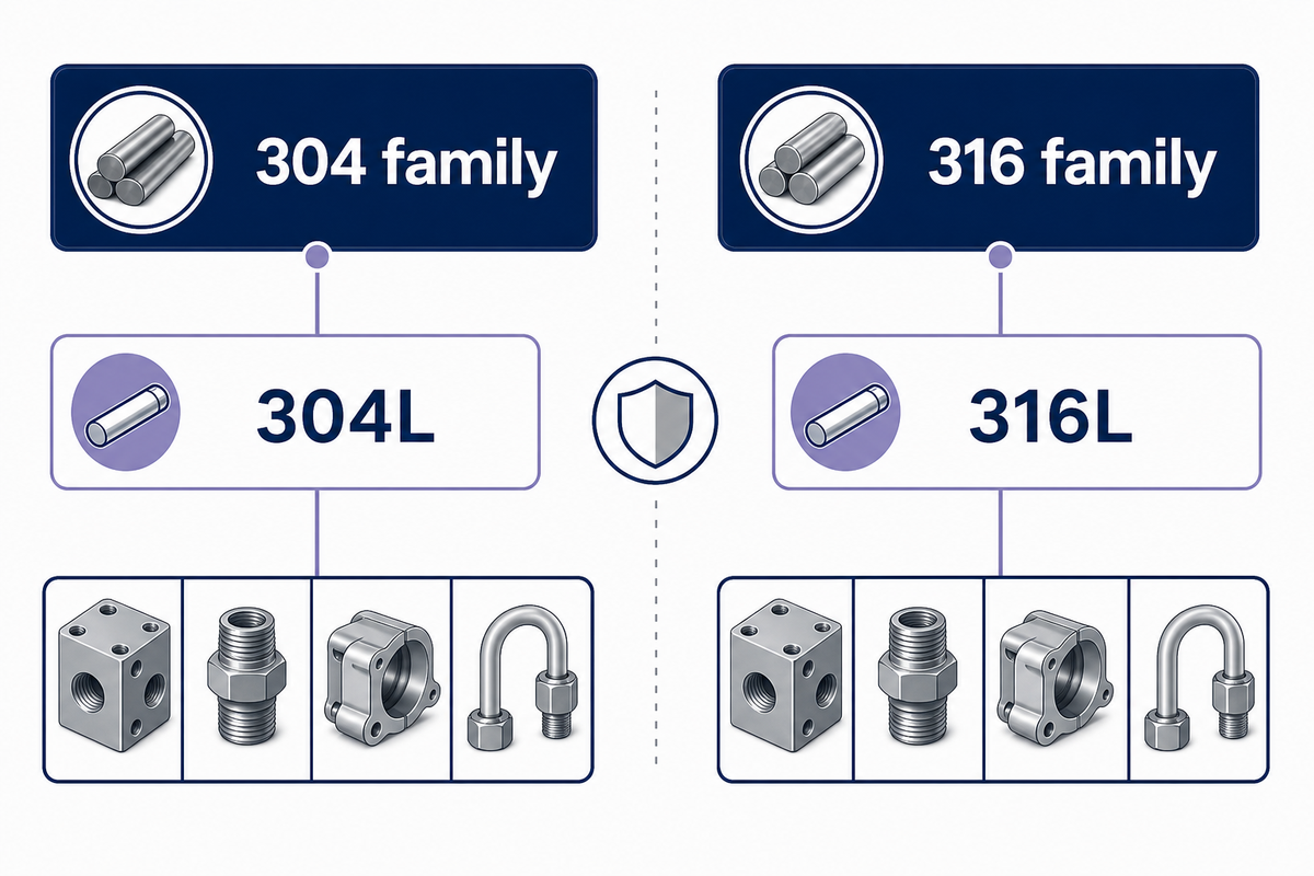
These grade designations are often regarded as a hierarchy. They’re better regarded as triggers for the subsequent question.
| Grade family | Useful directional meaning | Question it should trigger | Do not infer |
|---|---|---|---|
| 304 / 304L | Related 304-family designations; the label alone does not establish exposure or fabrication fitness. | Is the real chloride, cleaning, temperature, weld, and crevice exposure mild enough for the documented design? | That “stainless” means marine, chemical, or washdown suitability. |
| 316 / 316L | Molybdenum generally improves resistance to chloride pitting and crevice corrosion relative to 304 under comparable conditions. | Is 316-family material sufficient for this exposure, and is every wetted/exposed link compatible? | Immunity to seawater, bleach, trapped deposits, or chloride stress-corrosion cracking. |
Nickel Institute provides a useful counterexample to a universal ranking: substituting 316L into a 304L system is common, but 316L is not more corrosion-resistant in every chemical service. Its article cites nitric acid as one case where the normal intuition can fail. That is why a buyer should request an application basis, not just the highest-sounding grade.
Ask whether the stated grade applies to the complete body, valve element, cap, chain, spring, or only one named part. Mixed materials are not automatically wrong, but their corrosion, strength, thermal, galvanic, and joining relationships should be intentional.
Verify the Five-Link Diagnostic Compatibility Chain
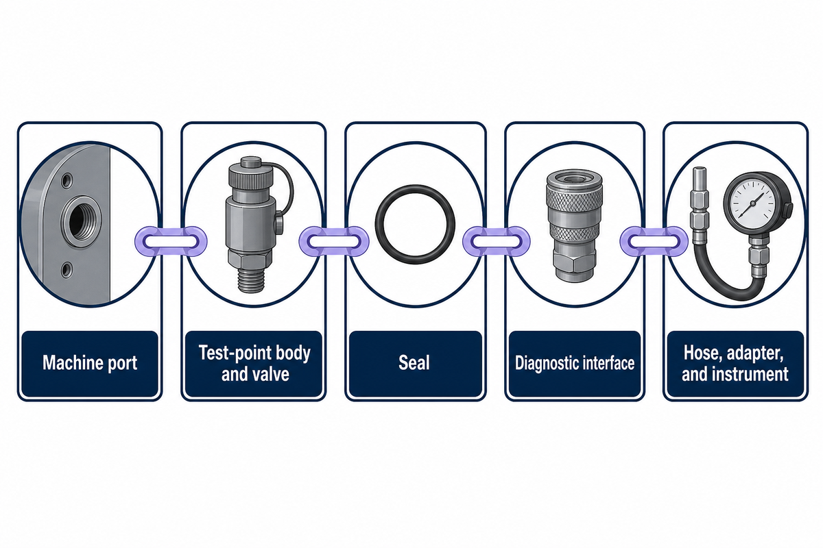
Five-Link Compatibility Reconciliation makes the full arrangement visible. Each link has its own identity, sealing method, material, pressure scope, and evidence. A supplier may provide several of those links, but the asset owner still needs to reconcile them with the machine and the intended measurement.
| Link | Record these fields | Common hidden mismatch | Release evidence |
|---|---|---|---|
| 1. Machine port | Port standard, thread, sealing geometry, mating material, installation location, circuit identity. | Same-looking thread with a different seal seat; stainless fitted to a less-noble metal in a wet electrolyte. | OEM drawing, manual, approved asset record, or responsible engineering confirmation. |
| 2. Test point | Process connection, body/valve materials, seal, diagnostic end, pressure and temperature conditions, cap. | Grade applies only to one part; seal or valve material is omitted. | Exact drawing, specification, lot-linked order description, and stated limitations. |
| 3. Diagnostic interface | Interface standard, mating method, permissible connection state, cleanliness and cap condition. | M16x2 is mistaken for the machine-side port or for blanket interoperability. | Both halves identified to compatible documented scopes. |
| 4. Hose and adapters | Each end connection, bore, assembly identity, fluid, pressure/temperature scope, routing and condition. | One adapter or hose end has a lower or unknown rating. | Complete assembly record; no rating borrowed from a similar configuration. |
| 5. Instrument | Connection, range, permissible fluid, accuracy basis, condition, calibration/verification status, intended reading. | A valid connection produces a reading that is unsuitable for the decision. | Approved instrument record and a defined measurement purpose. |
Fluid compatibility crosses several rows. ISO’s public scope for the M16x2 diagnostic coupling is designed around mineral oil; other fluids require agreement between supplier and purchaser. A static material chart or a familiar elastomer name does not establish leakage behavior under every cyclic pressure, temperature, additive package, or cleaning exposure. Use the site’s fluid and seal review worksheet to structure the questions, then obtain component-specific evidence.
Pressure also crosses rows. The useful assembly limit is not the highest number visible on one component. Record working pressure, planned diagnostic pressure, and permission to connect or disconnect under pressure separately. If the numbers are known, the complete-chain pressure rating checker can compare entered values; it cannot approve an unknown configuration.
Hose length and routing remain part of the chain; a direct-mounted point does not extend the rating or evidence of any other link. The same applies when the machine port uses NPT or another process thread: the label must be reconciled with its actual sealing form before a hydraulic system pressure measurement or monitoring task advances.
What M16x2 and ISO 15171-2 Actually Tell You
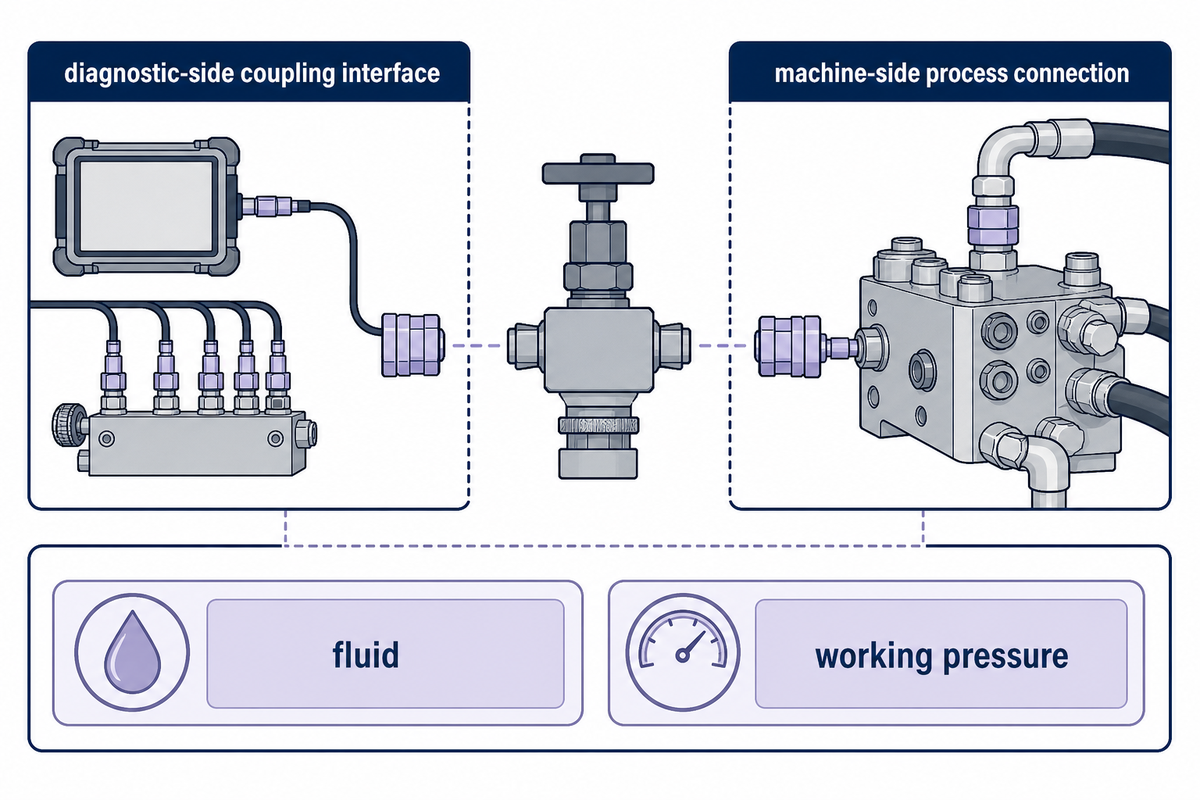
The official ISO catalog identifies ISO 15171-2:2016, Edition 2, for hydraulic diagnostic couplings with an M16 × 2 connection end. The page says the edition was confirmed in 2021 and remains current, while its lifecycle entered another systematic review in April 2026. That is a status note, not a new edition.
M16 × 2diagnostic connection end in ISO 15171-2
40 MPamaximum connect-under-pressure value in the public abstract
63 MPaconditional maximum working pressure in the public abstract
For unit normalization, 1 MPa equals 10 bar: 40 MPa is 400 bar, while 63 MPa is 630 bar. Converting the units does not merge the operating states or expand connection permission.
The two pressure values answer different questions. The public abstract describes connection under pressure without tools up to 40 MPa (400 bar). It also says conforming couplings may be used at a maximum working pressure of 63 MPa (630 bar), while warning that actual working pressure depends on materials, design, working conditions, and application. A product label of 630 bar does not automatically authorize connection at 630 bar.
M16x2 is also not the machine-side port identity. The ISO abstract lists several stud-end paths, including M14 × 1.5, G 1/4, and 7/16-20 UNF under referenced standards. The diagnostic end and the process connection need separate records. For a focused interface explanation, use the hydraulic test connection thread guide; for the standard-specific boundary, see the ISO 15171-2 compatibility guide.
Build an Evidence Pack That Follows the Delivered Lot
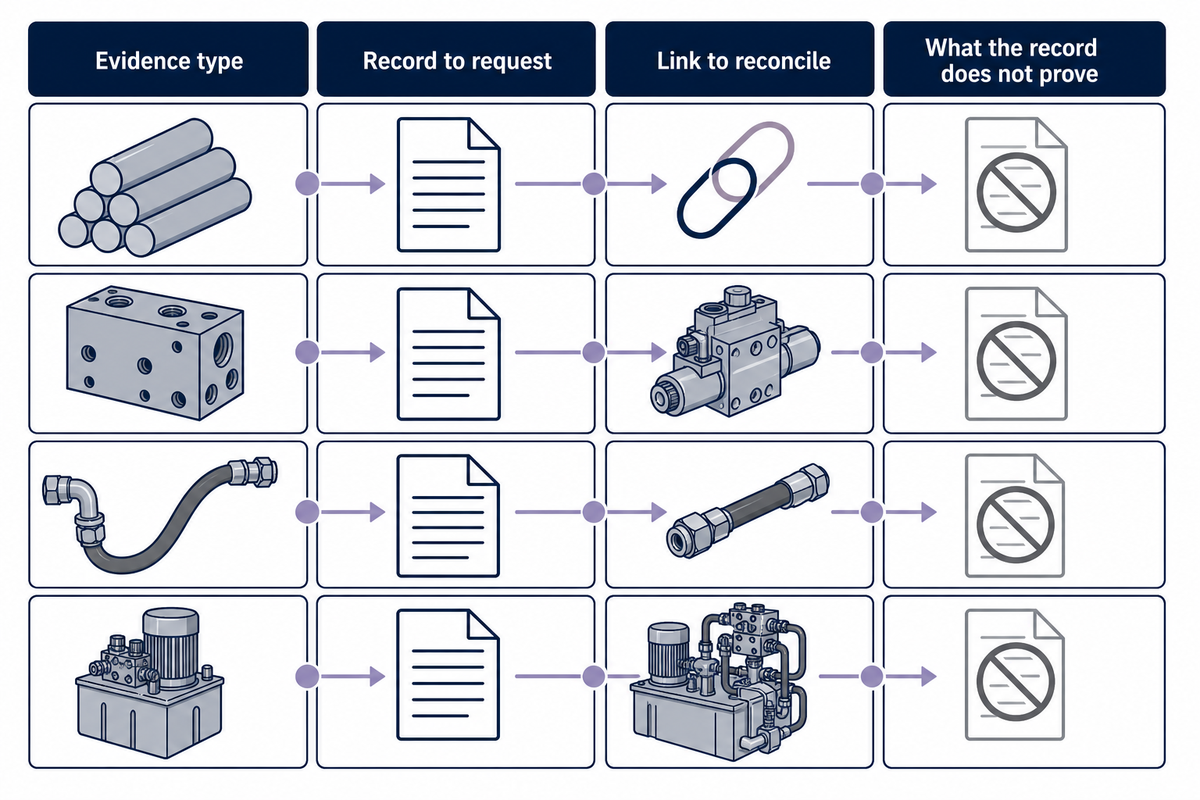
An evidence pack is useful only when each record answers a defined question and provides consistent traceability to the supplied parts. Without purchase-order, lot, heat, batch, or item linkage, a polished PDF may describe a material without attributing it to the shipment.
Lot-to-Claim Traceability Grid
| Evidence type | Record to request | Link to reconcile | What the record does not prove |
|---|---|---|---|
| Bulk material grade | Material declaration or inspection document with chemistry/mechanical results where contractually required. | Heat or lot identity on the record → manufacturing/inspection lot → delivered item or package marking. | Finished dimensions, seal compatibility, surface cleanliness, or application life. |
| Surface treatment | Specified cleaning, pickling/passivation process and test/acceptance record. | Treatment batch or lot → defined parts → invoked revision and acceptance criteria. | Bulk alloy identity, heat chemistry, or automatic suitability for the service. |
| Dimensions and interfaces | Approved drawing and dimensional inspection record. | Drawing revision → exact ordered model → inspection lot. | Pressure performance or fluid compatibility unless those tests are separately defined. |
| Pressure/leak test claim | Defined test method, whether scope is 100% or sample-based, acceptance criteria, equipment status, results, and lot. | Test record → inspected lot → delivered quantity. | Performance outside the test conditions or in an unknown assembled chain. |
| Seal and fluid compatibility | Exact elastomer designation plus supplier/application compatibility statement or representative validation. | Seal batch/model → test point variant → actual fluid/additive/temperature/duty. | Compatibility with another fluid or a materially different pressure cycle. |
| Process and diagnostic interfaces | Controlled drawing or specification for both ends and their sealing forms. | Interface designation → exact model → mating port, hose, or adapter. | That a similar-looking thread or nominal diameter will seal correctly. |
| Working-pressure scope | Product or assembly record stating the pressure basis, configuration, fluid, temperature, and limitations. | Rating record → exact component/assembly → actual application state. | Permission to connect, disconnect, inspect, or repair under pressure. |
| Connection-under-pressure permission | Applicable standard/product statement and both mating-component identities. | Permission → exact interface pair → planned connection pressure. | The higher working-pressure rating of either component or the whole diagnostic task. |
| Receiving condition | Incoming inspection record stating whether coverage is 100% or sample-based for quantity, identity, packaging, caps, threads, seats, contamination, and visible damage. | Inspection record → shipment/lot → disposition and owner. | Hidden chemistry, fatigue strength, or failure-free service life. |
The active public page for ASTM A967/A967M-25 illustrates the boundary. It covers passivation treatments and alternative tests for effectiveness, but its public scope explicitly does not recommend a grade, treatment, or acceptance criterion for a particular application. A passivation record can answer a surface-treatment question. It cannot replace material identity, dimensions, finished-part acceptance, or application review.
Similarly, even an extensive “100% inspection” program is incomplete unless the buyer knows what characteristic was inspected, by what method, against which criterion, with what equipment status, and how the record maps to the shipment. 100% visual inspection, 100% dimensional inspection, and 100% pressure testing are different claims.
Receiving and Safe Service Checks
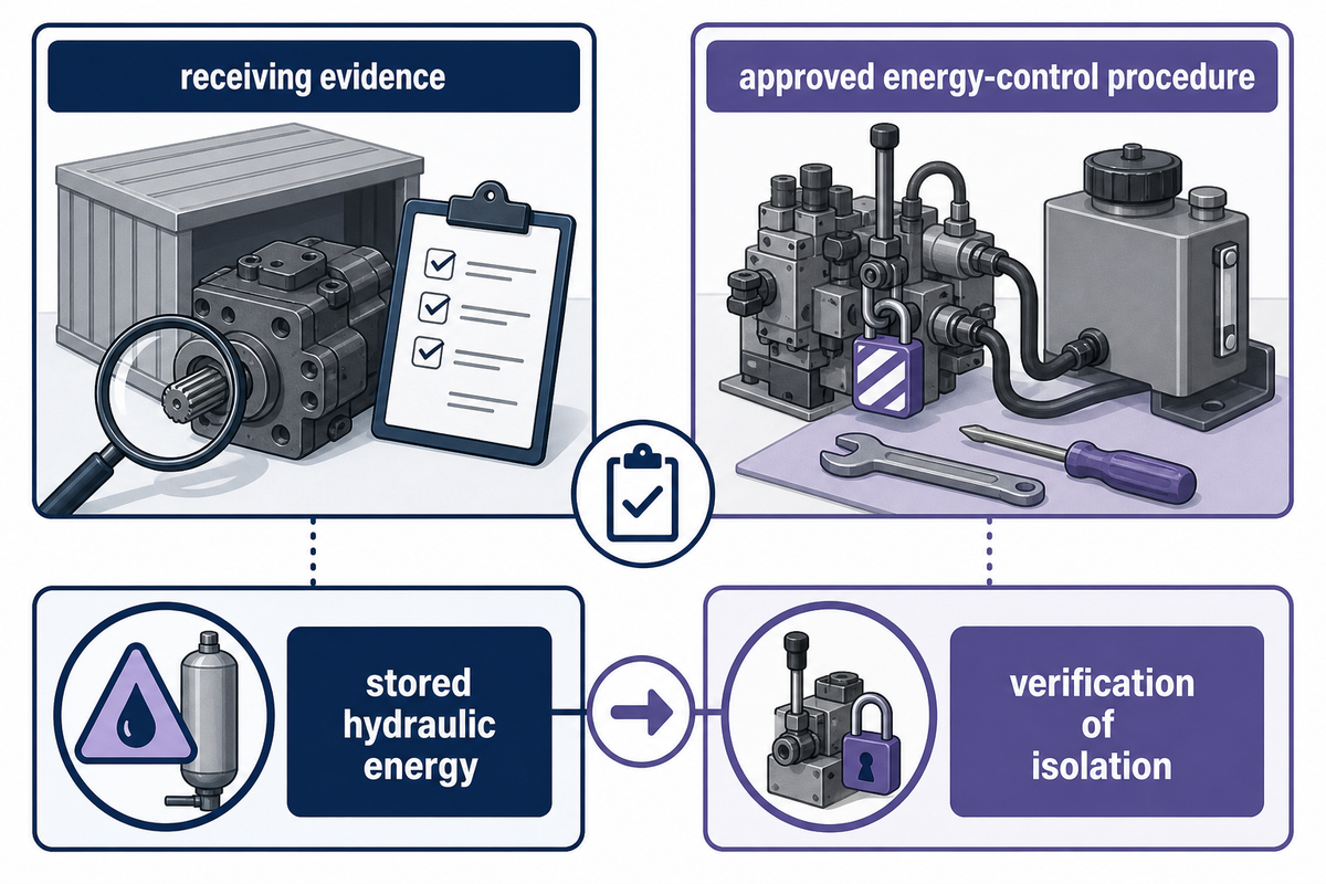
Inspection at receipt can identify mismatches before installation, but it has a limited scope. It can compare labels, documents, quantities, visual condition, accessible dimensions, presence of caps, and the ordered configuration. It cannot prove every chemical, metallurgical, pressure, or fatigue property without the appropriate analytical or destructive method.
- Reconcile identity — match purchase description, drawing revision, packaging, item markings, lot or heat references, and supplied records.
- Inspect condition — record damaged threads, sealing surfaces, caps, contamination, impact marks, staining, mixed hardware, and packaging damage without diagnosing the cause from appearance alone.
- Confirm interfaces — verify the process connection, sealing geometry, diagnostic end, and mating parts against approved records; do not test compatibility by forcing assembly.
- Close application fields — confirm fluid, temperature, pressure states, external exposure, mating-port material, seal, and authorized operating task.
- Release or hold — record GO only when required evidence is closed; otherwise assign HOLD FOR EVIDENCE or ESCALATE FOR APPLICATION REVIEW with an owner.
In US workplaces, OSHA 29 CFR 1910.147 addresses servicing where unexpected energization, startup, or release of stored energy can cause harm. Its definitions explicitly include hydraulic energy. Covered servicing calls for an energy-control program, isolation, control of stored energy, and verification. Where applicable to the actual machine, the site procedure may also need to address accumulators, gravity loads, blocking, trapped pressure, and potential re-accumulation.
Do
- Use the approved isolation and verification procedure for servicing.
- Describe visible symptoms before assigning a cause.
- Use documented leak-detection methods.
- Escalate unknown pressure or connection states.
Don’t
- Search for a pressurized leak with bare hands.
- Tighten or replace a point because live connection is permitted.
- Force a similar-looking thread to test fit.
- Treat zero gauge indication as proof that all stored energy is gone.
Read Rust, Seepage, and Cap Damage as Different Signals
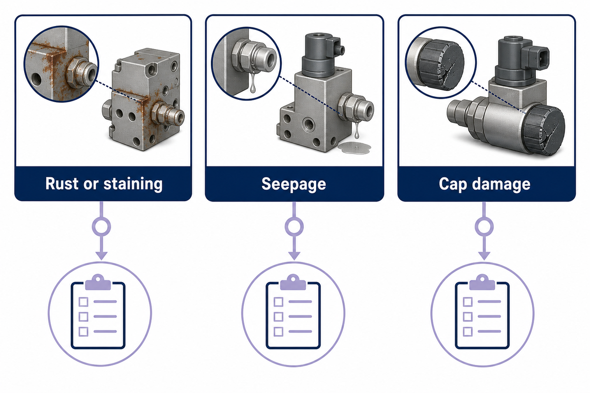
A symptom merely describes an observation, not a root cause. Brown staining may arise from free-iron contamination, carbon-steel debris, damaged surface condition, trapped deposits, a less-noble mating part, or localized corrosion of the stainless material itself. Slow seepage may originate at a seal, valve, seat, thread, adapter, or interface. Cap damage primarily raises contamination and protection concerns.
| Observed symptom | First questions | Evidence to collect | Unsafe inference to avoid |
|---|---|---|---|
| Brown staining | Is it removable surface contamination, pitting, crevice attack, residue, or corrosion of the mating component? | Location, morphology, cleaning history, exposure chemistry, photos, material/lot records, and qualified examination where needed. | “The body is the wrong alloy” based on color alone. |
| Slow seepage | Does it originate at the diagnostic valve, process seal, thread, hose connection, or adjacent component? | Isolated inspection under the approved procedure, seal identity, interface drawing, torque/installation record where applicable, and service history. | “Stainless failed” without locating the leak path. |
| Damaged or missing cap | Was dirt or moisture able to reach the diagnostic interface? Is the cap retention or sealing feature damaged? | Interface cleanliness, cap specification, environment, maintenance event, and mating-coupler condition. | That the cap is cosmetic or that replacing it alone restores cleanliness. |
| Thread or seat damage | Were the port and sealing form correctly identified? Was the part forced, cross-threaded, contaminated, or over-stressed? | Both mating-part identities, drawings, dimensions, damage pattern, and installation record. | That matching nominal thread size proves the sealing forms matched. |
When morphology, depth, material identity, or chemistry is uncertain, follow-up may involve qualified professional surface examination, positive material identification, or laboratory analysis. A blog cannot remotely diagnose the part. The safe editorial outcome is to define the evidence needed for a responsible disposition.
A Stop/Go Selection Workflow for Engineering and Procurement
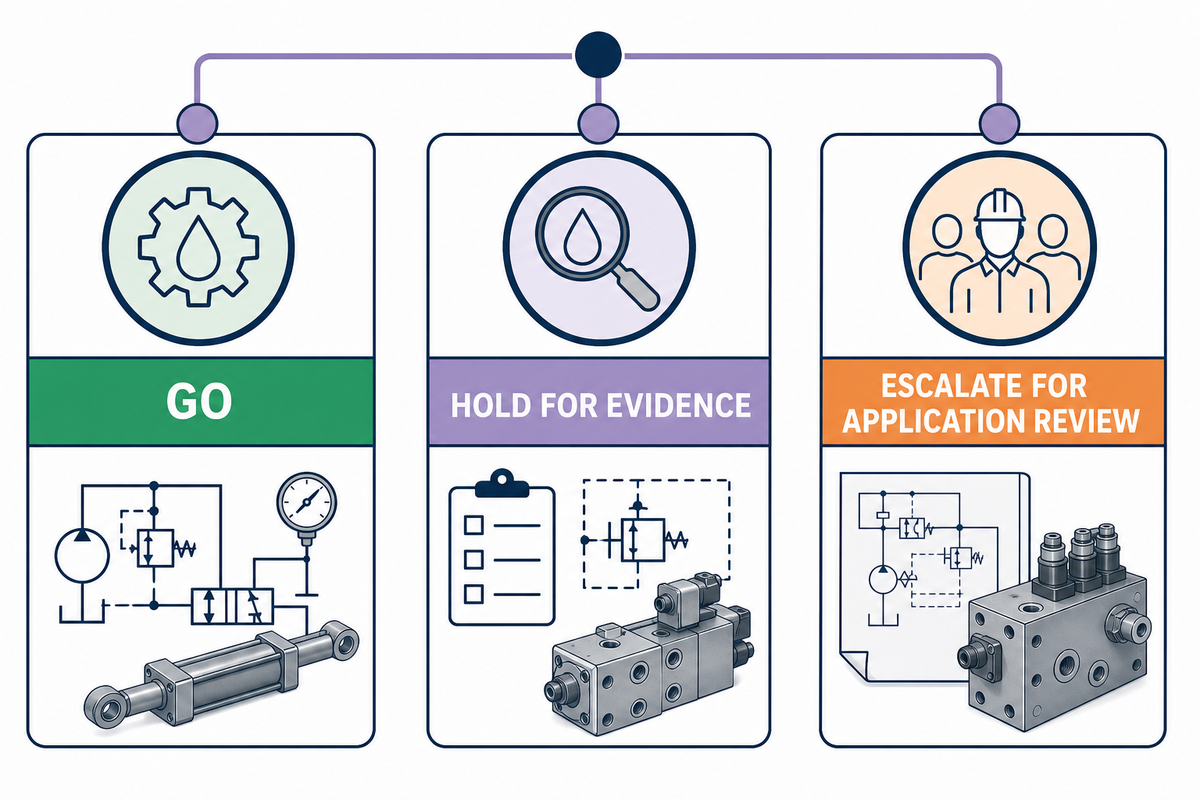
A selection workflow is useful only if it permits a stop. Forcing every inquiry toward a model rewards missing evidence and turns similarity into a decision rule.
| Decision state | Use when | Required action | Commercial model review? |
|---|---|---|---|
| GO | Exposure, both interfaces, mating material, seal/fluid, pressure and temperature states, diagnostic chain, and required evidence are documented within the proposed scope. | Release the defined requirement set to the responsible reviewer or supplier. | Yes, against the closed requirement set. |
| HOLD FOR EVIDENCE | The application is understood, but a drawing, rating, lot link, seal identity, test record, or other document is missing. | Name the missing record, owner, due date, and acceptance question. | No substitution by similarity. |
| ESCALATE FOR APPLICATION REVIEW | Fluid, chemical, temperature, galvanic, pressure-state, damage, or safety conditions fall outside a documented scope or remain uncertain. | Route to the equipment owner, responsible engineer, safety owner, materials specialist, or supplier application engineering as appropriate. | Only after the application boundary is resolved. |
Decision records should preserve the exact source revision and unresolved fields. That matters when a supplier changes a drawing, a fluid changes, a machine is rebuilt, or the same part number appears with different materials or seals.
The release sheet should preserve the ISO numbers in separate fields: 40 MPa (400 bar) for the public maximum connection-under-pressure statement, and up to 63 MPa (630 bar) for the conditional maximum working-pressure statement. Combining them into one “pressure rating” cell erases an important operational distinction the review is meant to protect.
“A complete-looking document pack is not the same as a complete compatibility decision.”
Move From Requirements to a Commercial Configuration
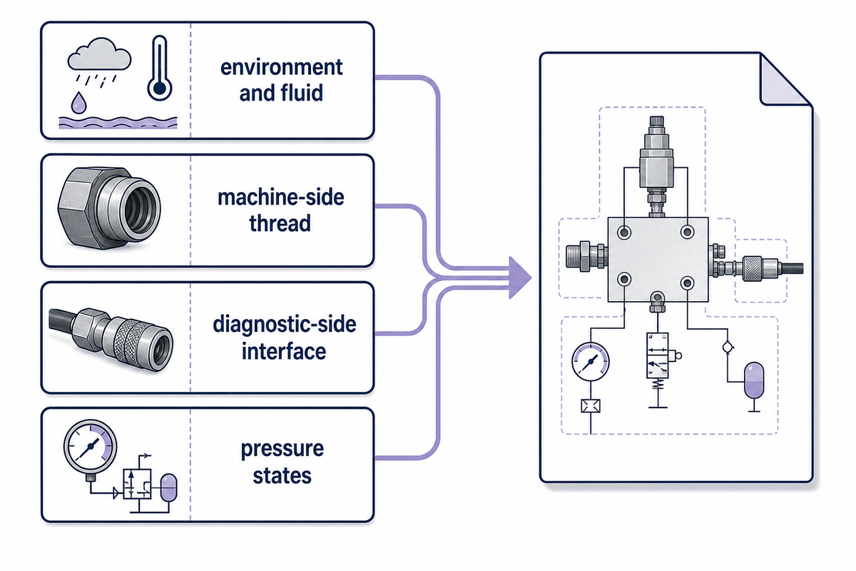
Once the requirement set is closed, use the stainless steel hydraulic test-point solution page to review available commercial configurations and start a drawing-based inquiry. Send the exposure summary, machine-side port and seal, diagnostic interface, fluid, three pressure states, temperature range, hose/instrument path, material requirement, quantity, and required inspection documents.
This handoff is intentionally short. Product range, supplier capability, quality-process claims, warranty, factory information, and quotation belong on the solution page and in controlled commercial documents, not in a competing guide aimed at the same head term.
Frequently Asked Questions
Are 316 stainless steel test points always better than 304?
No. Molybdenum gives 316 a useful directional advantage over 304 in many chloride-bearing environments, but “better” still depends on the actual chemical, temperature, deposit, crevice, stress, fabrication, and mating-material conditions. Some services can reverse the usual expectation or exceed both grades. Ask for the application basis instead of treating the grade name as a universal ranking.
Does M16x2 identify the machine-side hydraulic port?
Not necessarily. In ISO 15171-2, M16x2 identifies the diagnostic coupling end. The machine-side stud or process connection can follow a different thread and sealing standard, including one of several paths listed in the public abstract. Record both sides, their sealing forms, and the exact mating parts separately. A successful thread engagement is not evidence that the process seal or full connection is correct.
Can an ISO 15171-2 test point be connected at 630 bar?
The public ISO abstract distinguishes 40 MPa (400 bar) as the maximum connection-under-pressure value from a conditional maximum working pressure up to 63 MPa (630 bar). Product type, materials, design, working conditions, application, both mating components, and the complete diagnostic chain still govern. The higher number cannot be transferred into connection permission. If the connection state or exact product scope is uncertain, hold the task for evidence or application review.
Does a passivation certificate prove 316 stainless?
No. Passivation evidence addresses surface treatment; bulk alloy identity needs separate material evidence linked to the delivered lot. Neither record alone proves application fitness.
What should be included in a stainless test-point inquiry?
Include the equipment/port record, process connection and seal, mating-port material, diagnostic interface, hydraulic fluid and additives, external exposure, working/diagnostic/connection pressure states, temperature, hose/instrument route, material requirement, quantity, drawing revision, and required inspection evidence. Mark unknowns explicitly.
Does visible rust mean the stainless body is defective?
Not by itself. The stain may come from free-iron contamination, deposits, a mating component, surface damage, or localized corrosion. Isolate the system under the approved procedure and investigate the location, morphology, depth, material identity, and exposure before assigning cause.
Can maintenance connect a gauge under pressure and then tighten a leaking point?
No general permission follows from connection-under-pressure capability. Diagnostic connection and servicing are different operations. Tightening, leak investigation, replacement, or repair must follow the applicable energy-control, depressurization, and equipment procedures.
References & Sources
- ISO 15171-2:2016 official catalog entry and abstract detailing diagnostic use, M16x2 connection size, pressure-state terminology, specified stud configurations, fluid recommendation, and product lifecycle.
- Nickel Institute: Nickel in process engineering providing context for qualified usage of 304/316 material, including chloride and cleaning considerations.
- Nickel Institute: Stainless Steel Mix and Match, Some Do’s and Don’ts non-universal grade substitution and mixed-alloy cautions.
- ASTM A967/A967M-25 official catalog and public scope — passivation-treatment and acceptance-boundary context.
- OSHA 29 CFR 1910.147: The control of hazardous energy — US servicing and stored hydraulic-energy context.
Source review date: August 29, 2026. Standards and regulations can change; verify the current controlled documents for the application.
PAGE & COMPANY CONTEXT
This page is intended to help industrial buyers understand a practical hydraulic diagnostic path: test point, microbore hose and pressure-gauge connection.
For the site’s published company background, visit About. For inquiry details, visit Contact; information-handling details are available in the Privacy Policy.
TIME HYDRAULIC / IKIN
Hydraulic test-connection context for business inquiries
- Manufacturing context
- Changzhou Time Machinery Technology Co., Ltd., Changzhou, Jiangsu, China.
- Trade and export context
- Shanghai Ikin Hydraulic Co., Ltd.
- Product focus
- Hydraulic test points, DN2/DN3/DN4 microbore hose assemblies and pressure gauge connectors.
Since 2017
The public About page describes production activity since 2017.
Site-stated scale
The public About page states a 5,000 m2 plant and supply to 40+ countries.
Site-stated controls
The public About page describes ISO 9001, SGS, 100% inspection and a three-year warranty.
