Get in touch with TIME Company


![Hydraulic Test Point Selection Guide [8 Checks]](https://timehydra.com/wp-content/uploads/2026/08/hydraulic-test-point-selection-guide-featured.png)
Hydraulic diagnostic selection guide
A Hydraulic Test Point Selection Guide is a procurement and engineering checklist for matching a hydraulic test point with the correct port thread, coupling, pressure gauge, test hose, seal style, adapter, and documentation. Use this guide to specify the port, thread, pressure limit, hose bore, seal style, and RFQ data before a misordered fitting reaches the machine.
TIME Hydraulic manufactures hydraulic test points and hoses under the IKIN trademark. This engineering guide uses public standards, safety sources, and TIME product evidence; it’s a selection guide, not a live hydraulic pressure test procedure.
Fast answer: choose a hydraulic test point by confirming the machine port thread, diagnostic coupling family, pressure capability, hose bore, seal style, gauge or instrument, material, and document scope. Pressure rating doesn’t prove a correct fit, and a correct thread doesn’t prove the assembly is safe at that pressure.
What a Hydraulic Test Point Does in a Fluid Power System
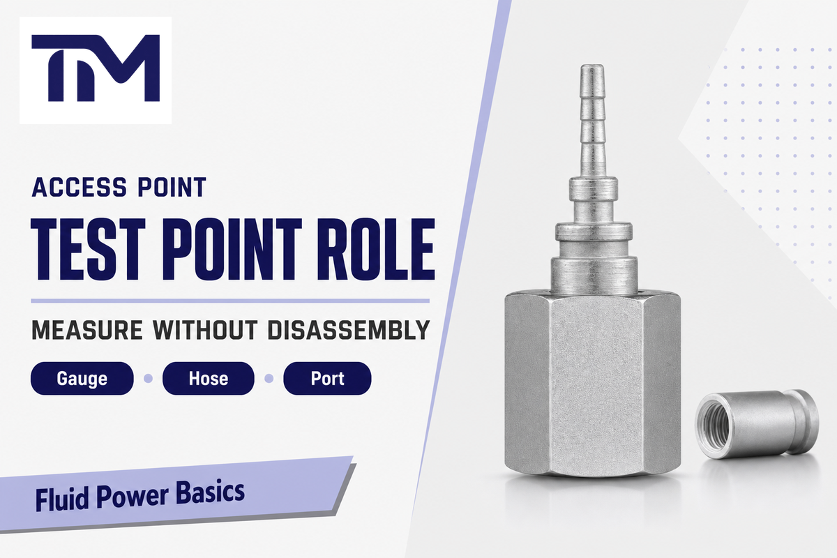
A hydraulic test point is a protected access interface for temporary pressure measurement, system diagnostics, pressure monitoring, and test hose connection. It gives a technician a controlled measuring point without leaving a pressure gauge permanently exposed on the machinery. Sampling belongs here only when the port, coupling, fluid, and procedure are designed for sampling.
In practice, a self-sealing valve or diagnostic coupling lets a technician connect a compatible test point fitting, hose, and pressure gauge when a circuit needs checking. Interface discipline is the hard part. The buyer must connect the machine, the instrument, and the rated hydraulic components without guessing.
Public standards keep that boundary narrow. ISO 15171-2 covers hydraulic diagnostic couplings with an M16 x 2 connection end. SAE J1502_202205 covers different diagnostic coupler stud ends, including M14 x 1.5 and 9/16-18. That split is why a real selection process starts with the exact coupling family, not a generic name on a catalog page.
Procurement objection: if a maintenance photo only shows “test port,” ask for thread, seal face, coupling standard, and target instrument. Photos can narrow the search, but they can’t verify pressure range, compatibility, or the required adapter.
Match Test Point Fittings, Port Standard, Test Coupling, and Pressure Rating Together
For selection support, review hydraulic test point product families when the specified connection family matches the drawing and operating conditions.
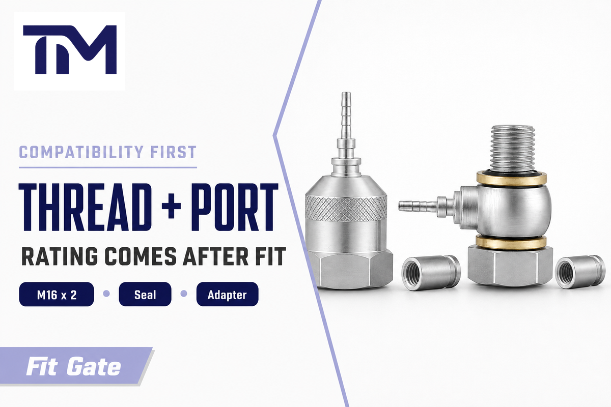
Thread, port standard, coupling geometry, and pressure capability are parallel gates. Even a rated hydraulic test point can still be the wrong fitting. Correct dimensional fit can still fail the pressure requirement. Treat fit and pressure as one compatibility review, then check the gauge and hose assembly around that decision.
One catalog word can hide several standards. M16 x 2, BSP, NPT, National Pipe Thread, metric stud ends, JIC, O-ring face seal, and 24 degree cone connections solve different interface problems. TIME’s end fitting page lists BSP, NPT, metric, JIC, and M16 x 2 connection ends, so a buyer should specify both the machine side and the instrument side before confirming price or lead time.
Use the machine drawing to anchor the order. A hydraulic test point fitting isn’t a generic piping and plumbing fitting; its pressure class, seal face, and diagnostic coupling family all have to match the hydraulic equipment.
Catalogs may call the same diagnostic line a Minimess hose, Minimess coupling, test point coupling, hydraulic pressure test hose, or M16x2 fitting. Treat those words as search and RFQ clues, then verify the actual thread, seal face, pressure limit, and instrument connection on the drawing.
The ISO 15171-2 diagnostic coupling scope and SAE’s diagnostic coupling page add a useful warning: dimensional conformance alone doesn’t prove rated performance. In plain terms, the thread can screw in and still be unsafe for the job. HSE also flags incorrect pipe couplings and makeshift repairs as operator errors in high-pressure hydraulic systems. That’s the selection lesson: never let the fitting code replace the rating, seal, and procedure review.
Wrong order: pressure label first
- Starts with 400 bar, 630 bar, or a kit range.
- Checks thread only after the part looks close.
- Misses seal face, coupling family, and adapter stack.
- Can leave the gauge side or hose side under-rated.
Correct order: compatibility gates
- Identifies machine port, coupling standard, and seal geometry.
- Checks working pressure, burst pressure, and connect-under-pressure limit.
- Confirms hose bore, gauge range, and instrument connection.
- Uses OEM instructions for pressure release and maintenance access.
Procurement objection: when a supplier quotes “same as M16,” ask whether the part follows ISO 15171-2 diagnostic coupling geometry or only shares a thread pitch. Same pitch is not the same as same test coupling.
Pressure Rating: Working Pressure, Burst Pressure, and ISO 15171-2 Connection Limits
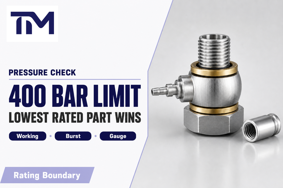
Pressure rating needs four separate checks: system working pressure, gauge pressure range, hose and coupling working pressure, and any connection under pressure limit. ISO 15171-2 gives a clear 40 MPa and 63 MPa boundary for its M16 x 2 diagnostic coupling context, but that pair is not a universal hydraulic test point rule.
For ISO 15171-2 M16 x 2 diagnostic couplings, the public ISO page lists connection under pressure to 40 MPa, or 400 bar, and maximum working pressure of 63 MPa, or 630 bar. TIME’s custom hydraulic test hose assemblies and DN2/DN3 microbore hose evidence use the same 400 bar and 630 bar references. Keep that wording inside the same coupling family unless another standard or supplier drawing supports the other part.
“Fluid released from a hydraulic system can be injected under the skin and lead to injury.”
That safety boundary changes the buying method. OSHA describes a hydraulic system modified from 3000 psi to 5000 psi while hoses rated for 3000 psi stayed in place; the hose coupling failed. This selection guide carries that lesson without turning into a safety procedure: the usable assembly pressure is limited by the lowest-rated hose, adapter, seal, gauge, coupling, and other system components in the connection path.
| Check | What to verify | Evidence boundary | Buyer action |
|---|---|---|---|
| 1. Coupling family | ISO 15171-2 M16 x 2 | ISO page scope | Ask for standard and thread on drawing. |
| 2. Connect under pressure | 40 MPa / 400 bar limit | ISO 15171-2 context | Do not use as a disconnect rule outside OEM instructions. |
| 3. Maximum working pressure | 63 MPa / 630 bar | ISO and TIME pages | Check every assembly component against this ceiling. |
| 4. Hose pressure | Working and burst ratings | Hydrotechnik/TIME matrices | Record the lower rating in the RFQ. |
| 5. Gauge range | Range suited to expected reading | Kit and gauge evidence | Avoid using gauge range as assembly rating. |
| 6. Adapter stack | Each adapter pressure class | OSHA lowest-rated lesson | Reject unverified adapter substitutions. |
| 7. Seal condition | Cone, O-ring, or face seal | ISO 8434-6 and supplier drawings | Confirm seal family, not just thread. |
| 8. Maintenance access | Pressure release and guarding | HSE guidance | Follow OEM and site procedures. |
| 9. Documentation | Pressure report or certificate scope | Sarum/TIME evidence | Name required reports before quotation. |
Procurement objection: if one line item says 630 bar but the gauge, adapter, or hose end has a lower limit, use the lower number for the assembly. The page’s highest number is not the working limit of the installed measurement path.
DN2, DN3, or DN4: Select Hose Bore by Gauge, Flow, and Access Space
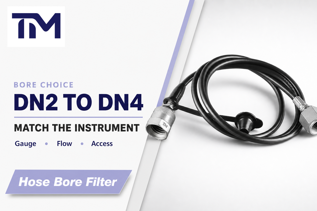
Hose bore selection should match the instrument and measurement path rather than pressure rating alone. DN2 and DN4 have public benchmark evidence, while ISO 15171-2 keeps the diagnostic coupling pressure boundary separate from bore choice. DN3 appears in TIME first-party microbore hose evidence, so treat it as a supplier-specific intermediate choice until the drawing confirm inner diameter, pressure rating, and fitting options.
Hydrotechnik lists DN2 as 2 mm and DN4 as 4 mm microbore hose material. TIME’s DN2 and DN3 microbore test hoses support routine gauge checks and tight installations, while TIME’s DN4 hydraulic test hoses can be specified for flow-based instruments, required flow, fast fill and bleed, and dynamic work where the instrument calls for it. ICS Schneider adds the counterpoint: a microbore hose can slow a pressure signal, so length, fluid condition, air, viscosity, expansion, and restriction should be checked before treating a larger bore as an accuracy upgrade.
| Instrument type / use case | Likely bore path | Critical question | Risk if ignored |
|---|---|---|---|
| Routine gauge reading | DN2 | Is response time acceptable for steady pressure? | Needless bulk in confined spaces. |
| Permanent monitoring point | DN2 or direct sensor | Will vibration or heat damage the gauge? | Gauge failure or unreadable pointer. |
| Tight mobile machinery access | DN2 or DN3 by drawing | Can the hose route without bending stress? | Thread damage or kinked hose. |
| Intermediate supplier replacement | DN3 if specified | Does the supplier state bore and pressure? | Assuming DN3 from a fitting code. |
| Long measuring line | DN4 may help | Will volume and trapped air delay the reading? | Damped peaks or time-shifted pressure. |
| Flow tester connection | DN4 or larger test assembly | What flow does the instrument require? | Starved instrument or misleading result. |
| Fast fill and bleed | DN4 | Does the task need larger volume flow? | Slow setup and trapped air. |
| Peak capture | Instrument-led choice | Can the path capture a short pressure spike? | Smooth traces can hide transient peaks. |
| Replacement hose order | Measure bore, not code | Does the RFQ state free length between fittings? | Correct thread with wrong hose response. |
Procurement objection: if a buyer asks for DN4 because “larger is better,” ask what the instrument measures, how long the hose will be, and whether the problem is steady pressure, fill/bleed speed, or transient response.
Cone Seat, O-Ring, Screw-to-Connect, or Push-to-Connect: Seal Style Tradeoffs
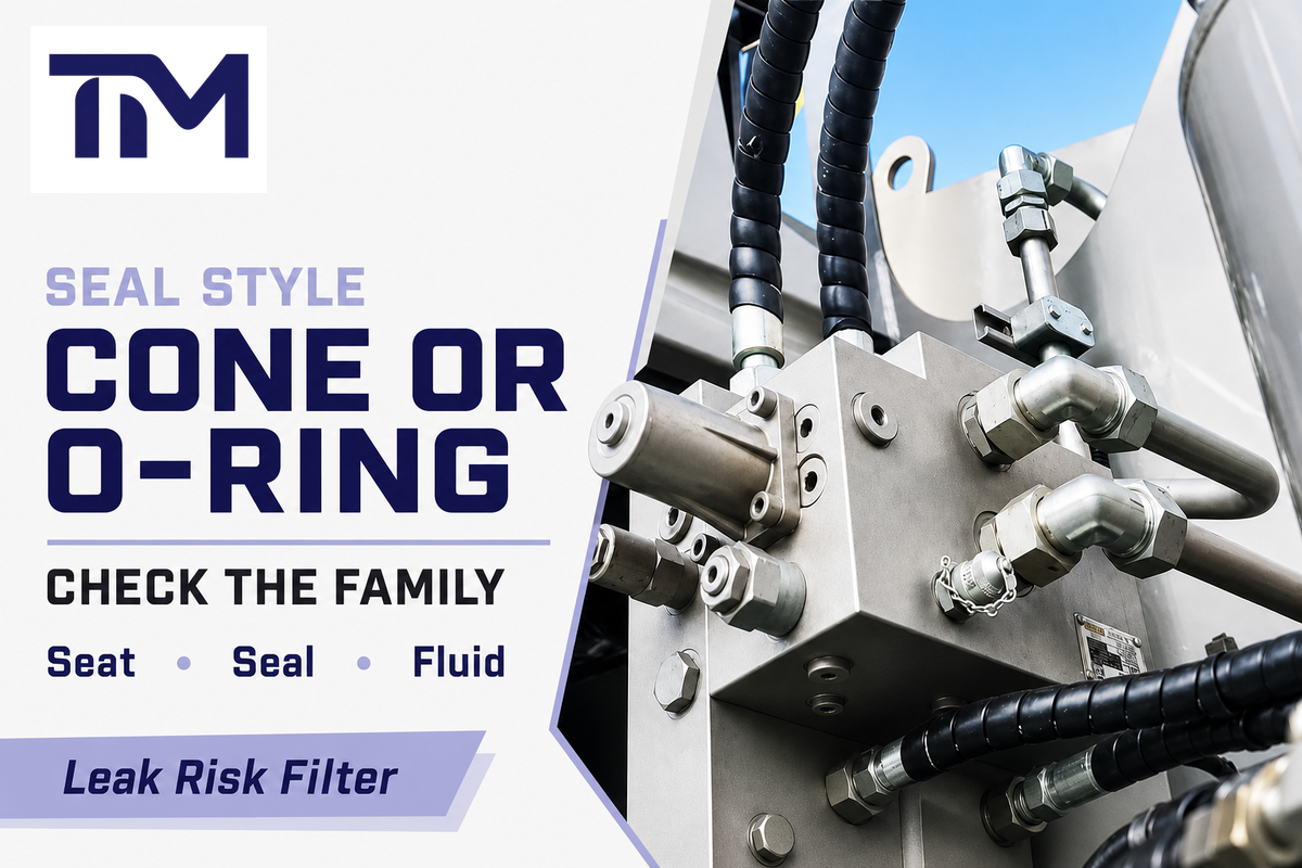
Seal style selection starts with the exact connector family. Cone seat, O-ring, screw-to-connect coupling, and push-to-connect coupling options solve different maintenance problems. ISO 8434-6 supports 60 degree cone connector context, but it does not prove a universal rule for every hydraulic test coupling style.
ISO 8434-6 covers 60 degree cone connectors and braze-on nipples with or without O-ring sealing. QC Hydraulics explains the field risk in practical language: mixing different cone systems can lead to leaks. TIME’s hydraulic test hose end fittings page gives buyer-facing options such as metal cone seat, elastomer O-ring, BSP, NPT, metric, JIC, M16 x 2, plated carbon steel, and stainless steel.
Use the RFQ to ask exact questions: What seal face is on the machine? What seal is on the test point fitting? Is the connection frequently made and broken? What hydraulic fluid, temperature, corrosion exposure, and pressure range will the seal see? Does the supplier inspect every assembly or sample a batch?
Procurement objection: don’t approve a seal style because the thread matches. Thread engagement can join two parts while the cone angle, O-ring location, or face seal is still wrong.
Pressure Gauge Placement and False Readings: Where the Test Point Should Sit
For selection support, review pressure gauge connector options when the specified connection family matches the drawing and operating conditions.
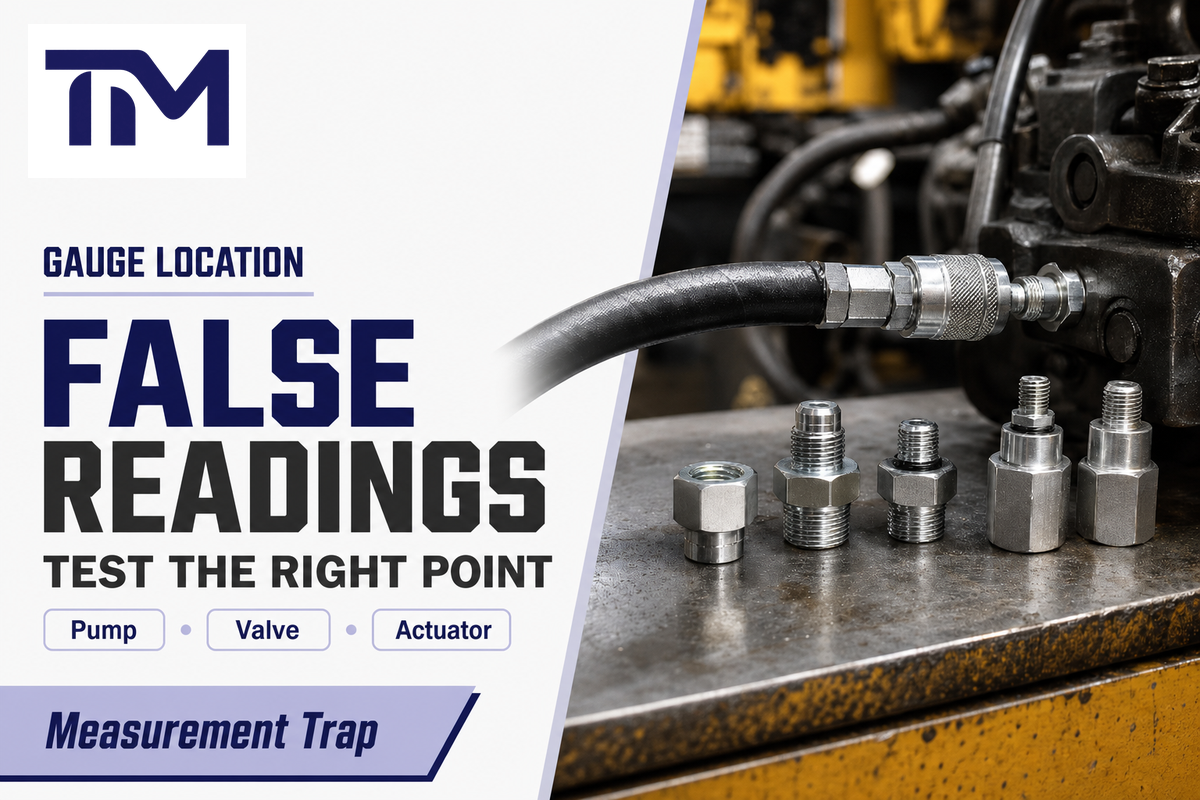
A normal pressure reading at one test point can miss a downstream restriction, actuator-side load, filter condition, or return-line issue. The pressure gauge reports its own location. Place the hydraulic test point near the diagnostic question, then choose the hose and gauge so the measuring path doesn’t distort the result.
Pressure gauge failures don’t always look dramatic. WIKA lists vibration, pulsation, temperature, pressure spikes, overpressure, corrosion, clogging, and mishandling as common reasons for pressure gauge failure. Pumps & Systems, quoting Hydraulic Institute pump-test guidance, flags inaccurate instruments and improper gauge location or installation as common testing problems. Field forum threads show the buyer-language version of the same issue: technicians often ask where to test instead of just what gauge to buy.
For a pump outlet question, use a point close enough to the hydraulic power unit to read supply pressure. For a control valve section, use the work port or a nearby diagnostic port that sees the load side. For hydraulic cylinders or a motor, compare the circuit point with the actuator-side question. For return line pressure, pressure drop, or filter restriction, one supply-side gauge can look normal while the machine still feels weak. Treat access and pressure release as a separate safety boundary: HSE warns that hydraulic fluid injection can cause major injury, and it lists incorrect pipe couplings and unreleased pressure among maintenance hazards.
Procurement objection: if one kit must serve several machines, specify adapter families and expected gauge locations. Portable hydraulic pressure test kit value depends on whether the connection set matches the real measuring points.
Hydraulic Pressure Test Kit and Instrument Match: Gauge, Flow Tester, Sampling, or Pump
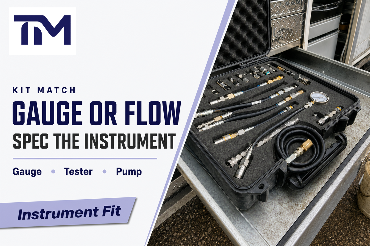
The test kit is a bundle, not a compatibility guarantee. Each hydraulic test point must match the instrument: pressure gauge, hydraulic pressure tester, flow tester, pump accessory, data logger, reference sensor, or a sampling setup designed for that job. Each instrument changes the connection, pressure range, hose bore, and adapter needs.
Discount Hydraulic Hose lists a hydraulic pressure test kit with gauges, microhoses, and ORB, NPT, BSP, and M16 x 2 test point adapters. Against the ISO 15171-2 M16 x 2 coupling boundary, that kind of kit evidence is helpful because it shows why the buyer must separate gauge range, hose, adapter, and test point fittings in the RFQ. It doesn’t prove the kit includes every connector on a machine.
When the task is pressure measurement, choose the pressure gauge range around the expected hydraulic system pressure and protect the gauge from pulsation and vibration. When the task is pressure control, flow control, or flow testing, the instrument may need a larger bore and a different hose route. When the task is sampling, don’t infer that every pressure test point supports it. State sampling only when the product and procedure explicitly allow it.
Procurement objection: a kit photo with a gauge and hose isn’t a bill of materials. Ask for gauge range, hose bore, length, adapter list, port standards, and the pressure limit for every connection in the kit.
Material, Cleanliness, and Documentation Checks for Procurement
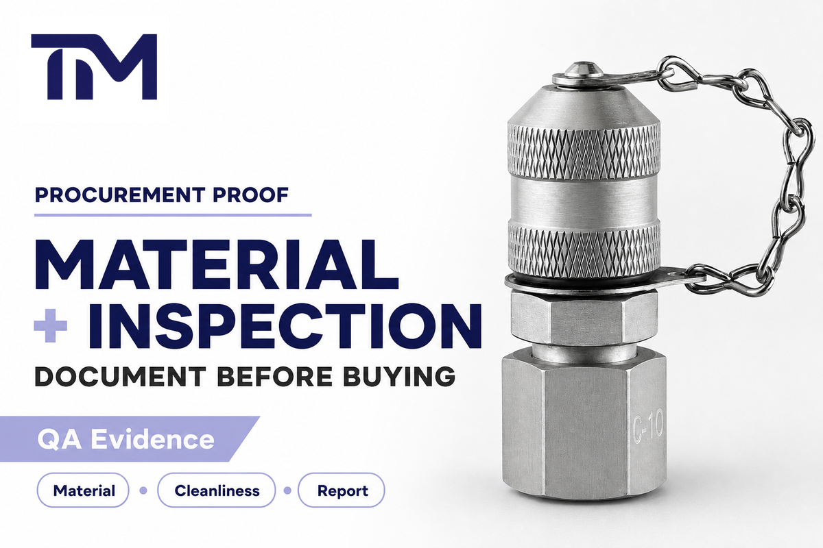
Material and documentation checks should separate safety-critical specifications from commercial purchase terms. OSHA’s hydraulic-system modification bulletin is a reminder to match hoses, couplings, and pressure before procurement labels; confirm material grade, plating, stainless steel option, corrosion exposure, fluid compatibility, pressure report scope, and inspection method first. Then add buyer-specific terms such as packing list, warranty, sample need, private label packaging, and lead time.
TIME product evidence supports zinc-plated carbon steel, nickel-plated steel, stainless steel 304, 316, and 316L options across hose and fitting pages, plus first-party inspection, traceability, pressure-report, and warranty language. Treat those as TIME capability signals and quote-specific RFQ fields, not as independent industry standards or a promise that every configuration ship with the same document package.
Sarum Hydraulics shows what a pressure test certificate often needs: order reference, certificate number, equipment serial number, medium, pressure, inspector, date, calibrated pressure gauge details, and traceability. That supports certificate fields when a project requires them. It does not mean every small replacement order needs the same full document package.
Cleanliness deserves a practical note. Hydraulic components with tiny passages can clog, and WIKA lists clogging as one reason a pressure gauge can fail or misread. If the assembly goes into hydraulic machinery, hydraulic equipment, oil and gas service, CNC machinery, high-performance hydraulic press service, sensitive manufacturing equipment, industrial machinery, or other industrial applications, ask how hoses are capped, packed, and identified after inspection. Accuracy and precision, plus durability, depend on the measuring path as well as the gauge.
Procurement objection: do not ask for “full documents” as a vague phrase. Name the certificate, pressure test report, material certificate, inspection record, packing list, and warranty term that the buyer actually needs.
RFQ Scorecard for OEM and Private-Label Buyers
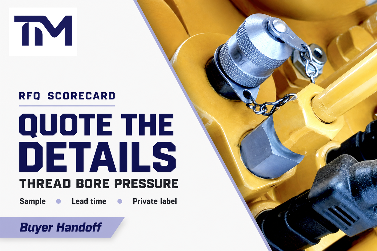
An RFQ for hydraulic pressure testing accessories should state technical fit fields before commercial fields. Use ISO 15171-2 or the supplier drawing to anchor the coupling family, then start with thread, port or coupling standard, hose bore, length, pressure limits, instrument, material, and inspection or certificate scope. Then add sample quantity, prototype timing, production lead time, warranty terms, branding, and packaging.
TIME Hydraulic specializes only in hydraulic test points and hoses. Reported company facts include ISO and SGS certifications, a 5,000 square meter production facility, new workshops under development, cone-seal zero-leakage designs, each-piece inspection, and a 3-year quality warranty. TIME public pages and supplied brand facts support the RFQ fields used here: test point fittings, DN2/DN3/DN4 hose options, material choices, inspection language, and warranty terms. Where a material certificate, pressure test report, packaging plan, or prototype lead time matters, put that exact document or timing requirement on the quote instead of assuming it applies to every configuration.
RFQ checklist – copy these into your quote request:
| Parameter | Recommended range | Why it matters | How to verify |
|---|---|---|---|
| Thread and port standard | M16 x 2, BSP, NPT, metric, JIC, or drawing | Prevents a rated but wrong fitting. | Machine drawing or sample part. |
| Coupling family | ISO 15171-2, SAE J1502, or supplier standard | Defines geometry and pressure context. | Standard reference on quote. |
| Hose bore | DN2 (2 mm), DN3 by drawing, or DN4 (4 mm) | Controls response, fill/bleed, and routing. | Bore and free length stated separately. |
| Pressure limits | 400 bar connection limit and 630 bar maximum only where supported | Avoids using one rating for the whole assembly. | Pressure report and component ratings. |
| Instrument | Gauge, flow tester, data logger, pump accessory | Changes hose and adapter selection. | Instrument port and pressure range. |
| Material | Plated steel, 304, 316, or 316L stainless steel | Matches corrosion, fluid, and cost targets. | Material certificate if required. |
| Inspection scope | Each-piece inspection where quoted, or agreed inspection plan | Controls leakage and delivery risk. | Inspection report or pressure test report. |
| Commercial fields | Sample, lead time, warranty, packaging, private label | Aligns purchase, inventory, and branding needs. | Quote line items and packing plan. |
For a maintenance buyer, the scorecard can reduce downtime because it turns a vague “send me the same hydraulic test hose” request into measurable details. For an OEM, it protects the approval file. For a distributor, it improves ease of use during substitute reviews because each offer can be compared by the same fields. That’s the practical value of selecting the right test fittings before the purchase order is issued.
Need a test point or hose quote?
Send TIME Hydraulic your thread, hose bore, pressure limit, instrument, material, and document requirements. TIME technical support can help diagnose the connection set, monitor hydraulic system pressure requirements, and match test point fittings, DN2/DN3 microbore test hoses, DN4 hoses, and custom assemblies.
FAQ
What is a hydraulic test point?
The hydraulic test point is a sealed access point used to connect a temporary gauge, test hose, pressure tester, or diagnostic instrument to a hydraulic system. This access point controls how the instrument connects to the machine, so it affects pressure measurement, pressure monitoring, and system diagnostics. It isn’t the gauge itself, and it shouldn’t be selected from pressure rating alone.
What are the different types of hydraulic test ports?
Common distinctions include the machine port thread, diagnostic coupling standard, seal geometry, connection style, and material. Examples include M16 x 2 diagnostic couplings, BSP, NPT, National Pipe Thread, metric, JIC, cone-seat fittings, O-ring designs, and hose assemblies built around DN2, DN3, or DN4 bore. The useful type name is the one that matches the drawing, not just the catalog family.
What pressure range should I choose for a hydraulic gauge?
Choose a pressure gauge range around the expected hydraulic system pressure, then check the gauge’s own rating, the test hose, coupling, adapter, and connection-under-pressure limit. Gauge range helps the technician read precise pressure, but it isn’t the working pressure of the full assembly. Don’t treat a 630 bar coupling claim as proof that the complete measurement path is safe at 630 bar.
How do you test hydraulics?
Use the equipment manufacturer’s procedure, release or control pressure as required, connect the correct test point fitting and gauge or instrument, then read pressure at the location that answers the diagnostic question. This article covers selection, not the live testing procedure.
What is the purpose of a hydraulic test?
Hydraulic testing checks pressure, system diagnostics, component condition, leakage risk, or system performance. Purpose decides where the test point should sit and which gauge, hose bore, coupling, and adapter should be selected.
Can a pressure gauge prove a hydraulic pump is good?
No. A pressure gauge proves pressure only at the measuring point and only under the test condition used. A pump may still have flow loss, internal leakage, control-valve bypass, suction restriction, heat, or actuator-side load problems. For example, low flow can let a no-load pressure check look acceptable while the machine slows under load. If the pump is suspect, test at the specified port, load condition, temperature, and engine or motor speed, then compare the reading with flow or cycle time.
Do I need two gauges for hydraulic troubleshooting?
Sometimes. Two gauges can compare pump outlet pressure with downstream circuit pressure, return line pressure, actuator-side pressure, or pressure drop across a filter or valve. The second gauge is useful only when the extra test point sits at a diagnostic location that answers a real question.
Why does my gauge needle flutter?
Gauge flutter can come from pulsation, vibration, pressure spikes, air in the measuring path, clogging, or a hose/instrument setup that damps or delays the signal. Start troubleshooting with the gauge location, then check hose length, bore, fluid viscosity, adapter restriction, and trapped air. If the system has fast control valves or a short pressure spike, the measuring path may smooth the event before the pointer can show it.
Why does my hydraulic system show normal pressure but still feel weak?
Normal pressure at one port can miss a flow restriction, worn actuator, valve leakage, return-line back pressure, or load-side problem elsewhere in the circuit. Move the test point to the part of the machine that feels weak, then compare pressure with flow and operating condition.
What should I send before ordering hydraulic pressure testing accessories?
Send the machine port thread, coupling standard, hose bore, free length, pressure limit, gauge or instrument, material, seal style, quantity, sample need, certificate scope, packaging, and lead-time target. Add photos only as supporting evidence, not as the full specification.
References & Sources
- ISO 15171-2:2016 hydraulic diagnostic couplings standard page
- ISO 8434-6:2009 60 degree cone connectors standard page
- SAE J1502_202205 diagnostic hydraulic couplings page
- HSE high pressure fluid injection hazards
- OSHA Hazard Information Bulletin: Hydraulic Systems Modifications
- Hydrotechnik DN2/DN4 microbore hose material reference
- WIKA pressure gauge failure causes
- Pumps & Systems Hydraulic Institute pump test FAQ
- Sarum Hydraulics pressure test certificate guide