
Get in touch with TIME Company

Bulkhead Pressure Gauge Connectors
Route a pressure gauge through a machine panel without treating one thread callout as proof of fit. TIME Hydraulic helps buyers define the gauge side, diagnostic side, panel geometry and evidence package before a model is quoted.
Through-panel purpose
Separate gauge placement from the diagnostic line while keeping both interfaces reviewable.
Current-model evidence
Use the submitted part number and drawing revision; a family image is not a compatibility decision.
Commercial starting point
Samples, custom-logo trials and bulk scheduling are available under the terms shown below.
Panel-Mounted Gauge Connections for Hydraulic Diagnostics
A pressure gauge bulkhead connector creates a mechanical pass-through between a gauge outside an enclosure and a hydraulic diagnostic connection behind the panel. It is useful when the gauge must remain visible or replaceable without moving the system-side line.
01
Gauge-side job
Hold the requested female gauge connection at the correct dial location and orientation. Record thread, seat or sealing method rather than writing only “NPT” or “BSP.”
02
Panel job
Pass through a known hole and panel thickness with access for the locking hardware. Leave enough room for assembly tools, gauge case and future replacement.
03
Diagnostic-side job
Mate with the specified hose, test coupling or system interface. Confirm the connection state and the evidence boundary for the entire measurement chain.
04
Thread-name gap
A thread name alone does not identify the seat, sealing method or mating geometry. Treat the label as one input, not the finished match.
05
Panel-fit gap
A gauge can match the thread and still create a wrong panel fit. Hole, thickness, access and orientation remain independent checks.
06
Pressure-chain gap
A maximum working-pressure figure for one item is not a substitute for complete-chain evidence. Keep the boundary visible on the selection record.
Bulkhead Pressure Gauge Connector Configurations
Our range includes bulkhead pressure gauge connectors for through-panel installation. The practical difference between models is the pair of interfaces and the mounting geometry between them, not the shared product label.
Request a Configuration Drawing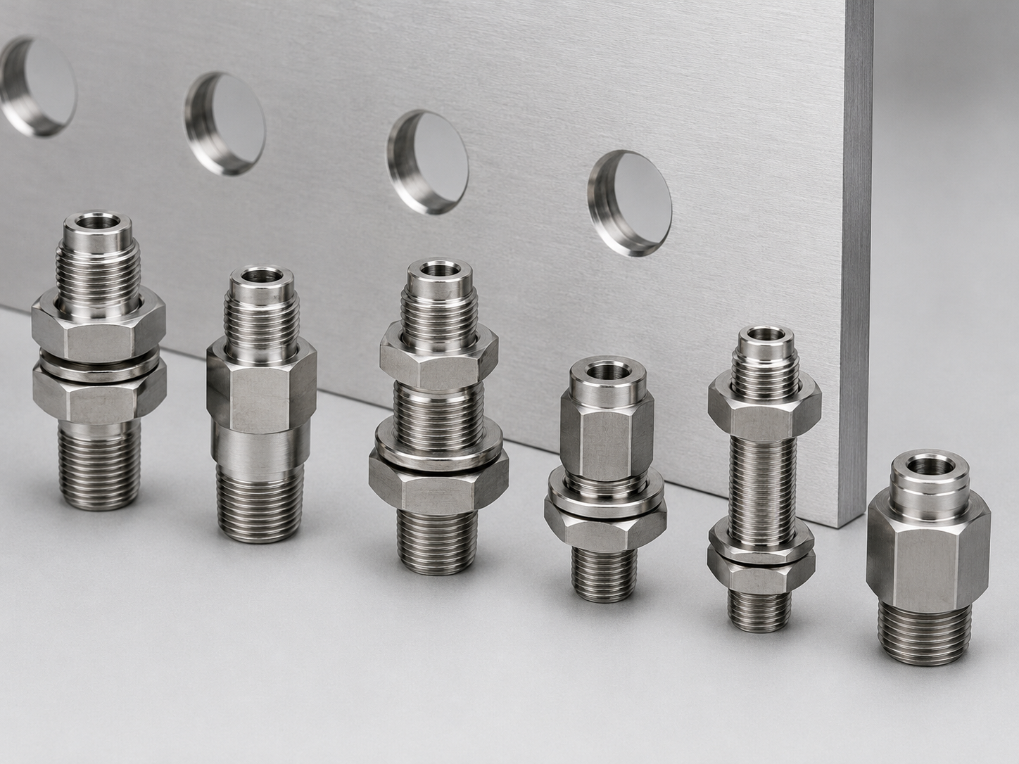
[ SPECIFICATION MATRIX ]
Input
Why it matters
Acceptable evidence
Unknown behavior
Gauge thread and seat
Prevents a nominal thread match from hiding a sealing mismatch.
Gauge drawing, marked sample or clear connection photo.
No model recommendation.
Diagnostic-side interface
Defines what the connector must mate with behind the panel.
Existing part number, drawing or measured interface record.
Quote remains configuration-pending.
Panel geometry
Controls hole fit, clamping and installation access.
Panel sketch with dimensions and accessible side marked.
Drawing approval is withheld.
Pressure and connection state
Separates operating conditions from a catalogue family number.
Model-bound qualification evidence and system requirement.
No pressure suitability statement.
[ CONFIGURATION VARIABLES ]
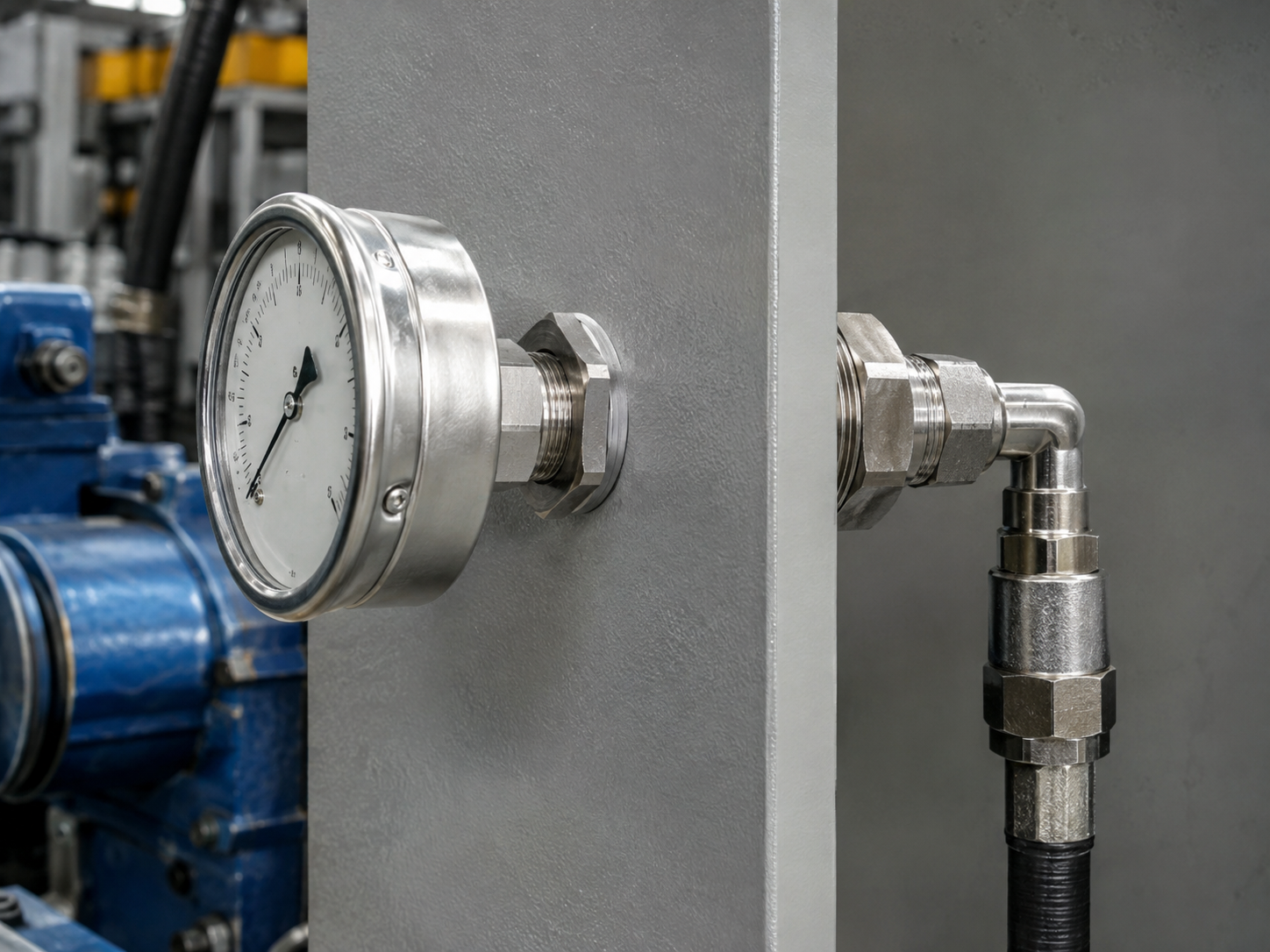
- 01 Female gauge connection
- 02 Male or female connection form
- 03 Thread family and nominal size
- 04 Seat, face or thread-sealing method
- 05 Back, lower or special gauge connection location
- 06 Gauge case clearance and dial direction
- 07 Diagnostic connection
- 08 Mating coupling or hose end
- 09 Thread and sealing geometry
- 10 Connected or disconnected pressure state
- 11 Required cap, plug or dust protection
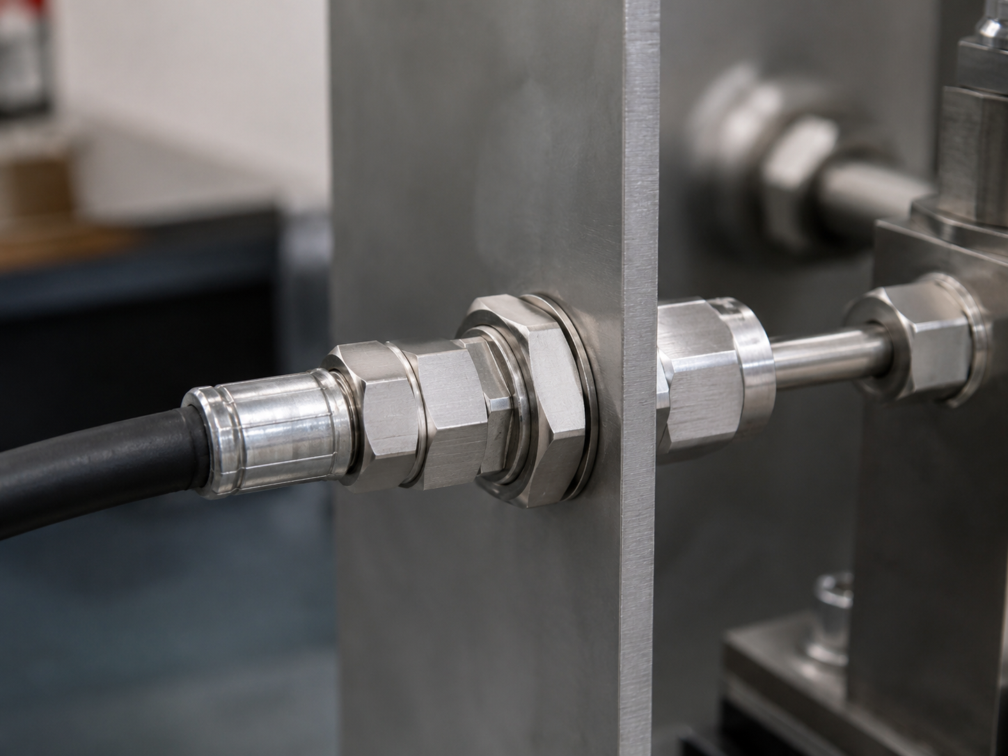
- 12 Bulkhead mounting
- 13 Panel hole and thickness
- 14 Locknut side and tool access
- 15 Anti-rotation requirement
- 16 Permitted body and gauge envelope
SOURCE NOTE
Selection input source: Pumps & Systems identifies connection type and mounting position as replacement inputs. TIME selection still requires both interfaces and the submitted mounting record.
Engineering Specifications
Materials, Coatings and Seal Options
Material choice is an exposure decision, while seal choice is a media-and-temperature decision. The connector body, gauge interface, diagnostic interface and adjoining hose should be reviewed as one chain rather than as isolated catalogue rows.
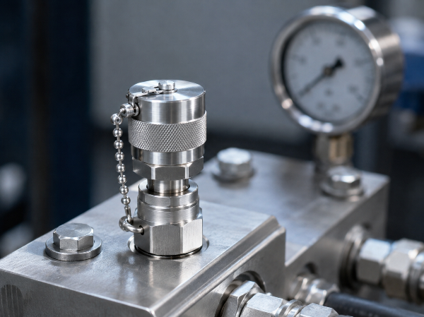
Body and surface
State the required base material, corrosion environment, washdown exposure and any coating restriction. Do not substitute stainless steel for coated steel—or the reverse—without checking the drawing and purchasing specification.
Seal definition
Name the exact compound, hydraulic fluid, temperature range and cleaning exposure. Generic labels such as “rubber seal” do not create an evidence-ready configuration.
Cone-seal scope
We use cone-seal geometry in selected hydraulic diagnostic connector designs. The drawing must identify whether that geometry belongs to the requested model and which mating surface completes it.
Panel Geometry and Drawing-Controlled Dimensions
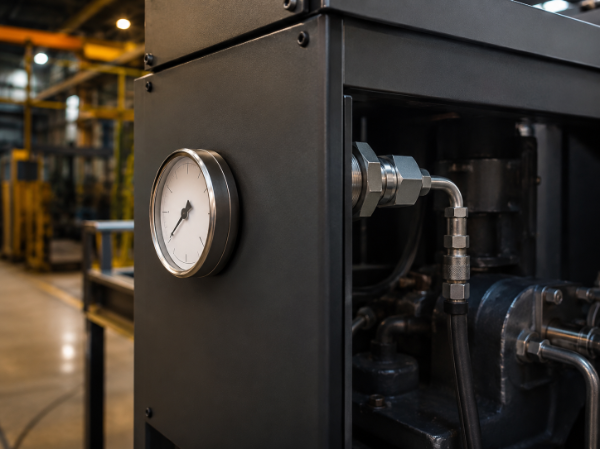
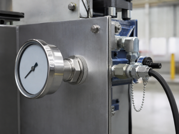
Gauge thread alone does not control panel fit. Whether a panel mount gauge connector can be installed and serviced depends on the hole, panel thickness, clamping stack, accessible side, dial orientation and surrounding service envelope.
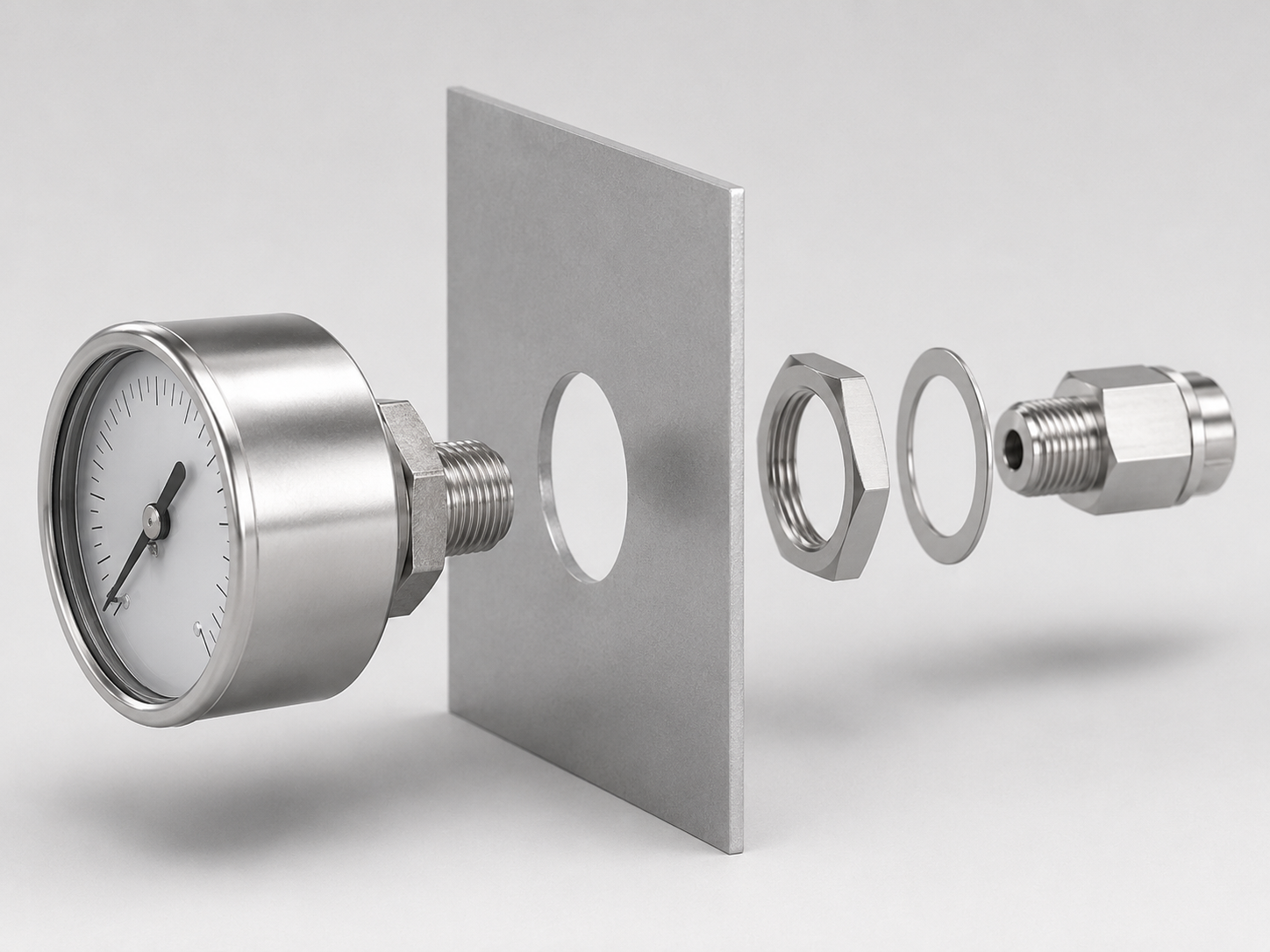
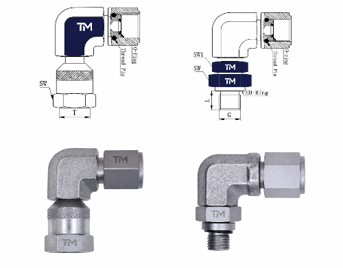
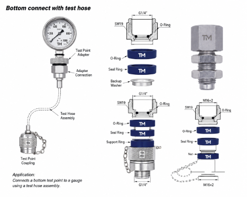
Legacy TIME application diagram. Use it to identify the mounting job; request the current drawing for model dimensions.
Real product-family image migrated from the old site. Visible shape is not proof of thread, seat or interchangeability.
- Panel hole diameter or drawing
- Panel thickness and material
- Front/rear accessible locking side
- Gauge case diameter, weight and connection location
- Required dial direction and nearby obstructions
- Body, shoulder and thread envelope
- Locking hardware and clamping stack
- Gauge-side and diagnostic-side callouts
- Seal position and mating surface
- Part number and drawing revision
SERVICE ENVELOPE / RISK CONTEXT
Wrong panel assumptions create a hidden fit risk because access and envelope are independent of the gauge thread. For service-space context, Fluid Power Journal reports its own 3 in diameter by 8 in high clearance guidance; TIME Hydraulic provides a candidate drawing for the actual panel review.
Pressure, Temperature and Media Evidence
Configuration & Envelope
A usable pressure statement names the exact configuration, pressure state, method, acceptance criteria and operating envelope. It also says whether the number applies to the connector alone or to the coupled hose, connector and instrument.
Measurement Route Controls
The lowest substantiated limit in the assembled measurement route controls. A component value cannot be promoted into a system value by marketing wording.

Operating input
Provide working pressure, possible transients, media, minimum and maximum temperature, and whether connection or disconnection occurs while pressure is present.
Evidence input
Request the applicable test or qualification method, specimen/configuration identity, acceptance threshold, date or revision, and component boundary.
Release decision
Compare the buyer requirement with the exact model evidence. If either side is incomplete, keep the model status “review required” instead of inferring suitability.
SPEC NOTES
Standards boundary: The SAE J1298 public record scopes diagnostic-port sizes and locations; it does not provide a TIME model pressure qualification.
Bulkhead Connector, Direct Gauge Adaptor or Remote Gauge Line
A bulkhead gauge adapter is one route of mounting, not the automatic solution to any gauge placement question. Before selecting the connector, consider access, vibration, temperature, media isolation, routing and replacement considerations.
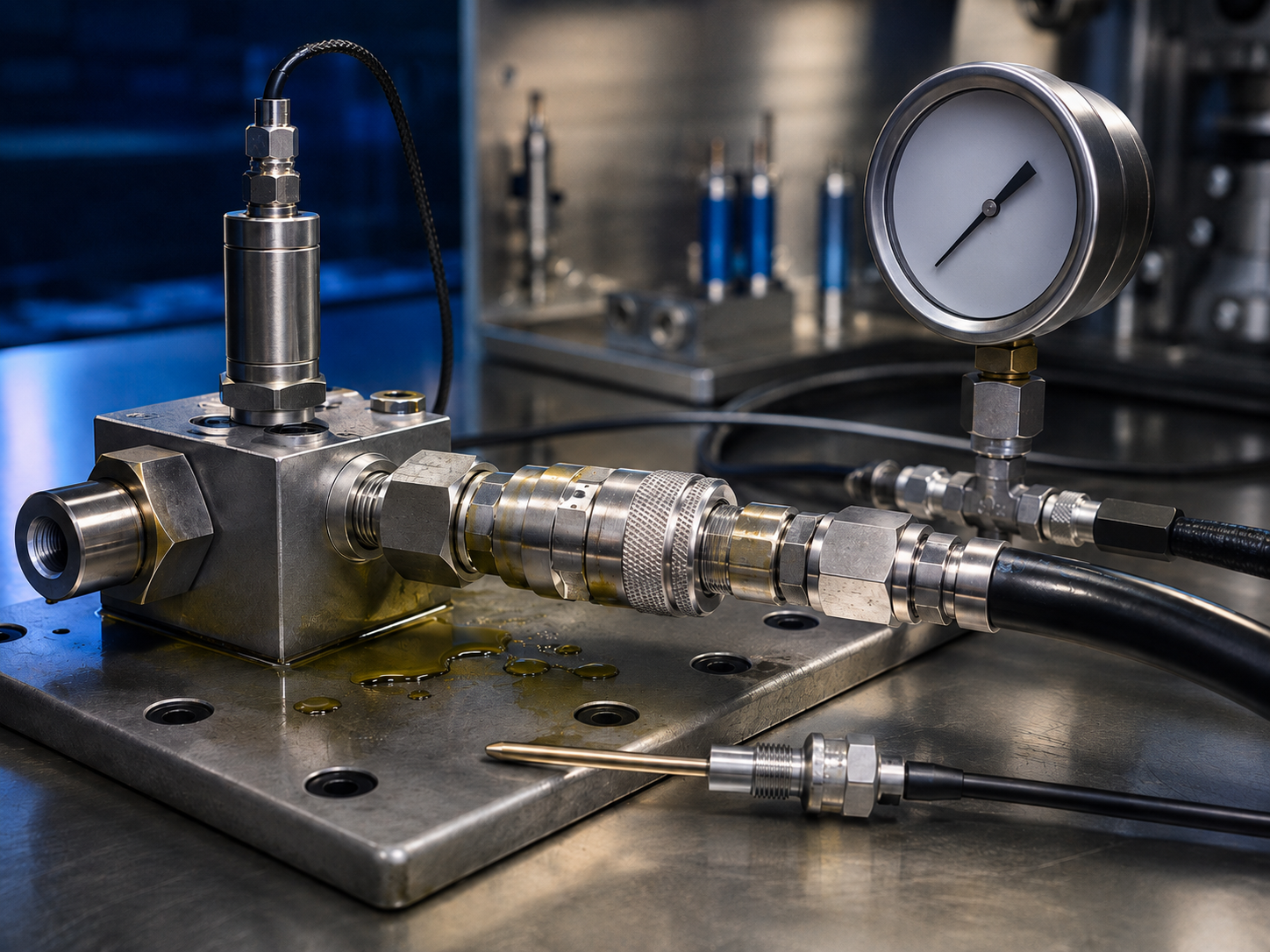
Bulkhead connector
Best-fit job
Gauge outside a panel, diagnostic line behind it, controlled pass-through location.
Review carefully
Panel hole, thickness, locknut access, gauge weight and orientation.
Evidence needed
Two interface callouts plus mounting drawing.
Direct gauge adaptor
Best-fit job
Gauge can sit at the measurement point and remains accessible.
Review carefully
Vibration, heat, clearance, gauge orientation and removal path.
Evidence needed
Gauge connection and process/diagnostic interface record.
Remote gauge line
Best-fit job
Gauge needs separation from heat, vibration, poor access or moving structure.
Review carefully
Hose route, protection, length, operator position and complete-chain limits.
Evidence needed
Line drawing, end connections and environment record.
Unlike a one-column catalogue choice, the route decision exposes the mounting job before a model is named. The trade-off is clear: a bulkhead connector organizes a panel pass-through, while a remote hose buys separation and costs you an additional routing and protection review.
TECHNICAL SOURCE: Remote-route source: Instrumentation Tools describes remote mounting for temperature, vibration and access constraints; final hose and connector selection remains model-specific. If the route uses a flexible measurement line, compare the required hydraulic test hose end fittings and document any custom test hose assembly before drawing approval.
COMMERCIAL FRAMEWORK
Samples, Trial Orders and Production Lead Time
Start with a confirmed configuration, then choose the smallest commercial step that produces useful evidence. Timing and price still depend on the drawing, material, quantity, evidence scope and accepted quotation.
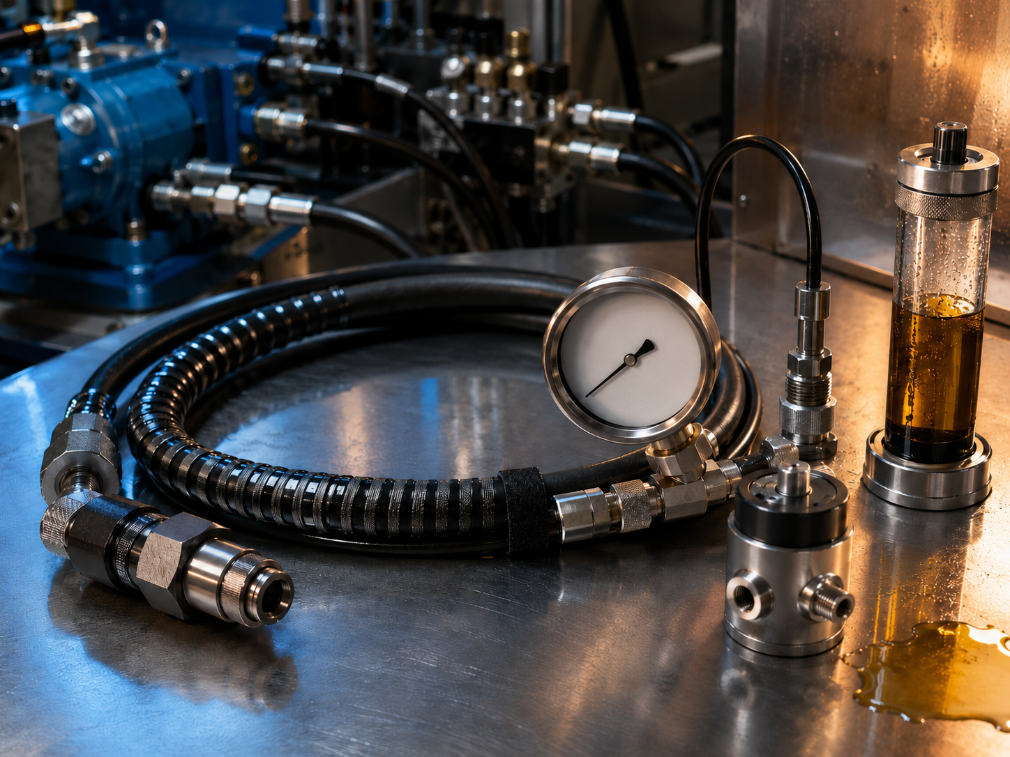
Commercial or company fact
TIME first-party term
Buyer action
01 Sample timing
Samples usually ship within 3 days after drawing approval.
Confirm sample cost and available configuration.
02 Sample policy
Samples are available but are not always free; they usually ship within 3 days.
Record the agreed charge on the quotation.
03 Custom-logo trial
Trial orders start at 100 pieces with a custom logo.
Submit artwork and drawing requirements.
04 Bulk production
Bulk orders are scheduled for 10–30 working days, confirmed with your quotation.
Confirm configuration freeze and shipment date.
05 Payment
T/T, 30% deposit and 70% before delivery.
Verify banking and order terms on the invoice.
06 Incoterms
We ship EXW, FOB, CIF and CFR; other Incoterms are reviewed on request.
Name destination and preferred responsibility split.
07 Warranty
These connectors carry a 3-year quality warranty.
Request the applicable warranty terms with the quotation.
08 Facility
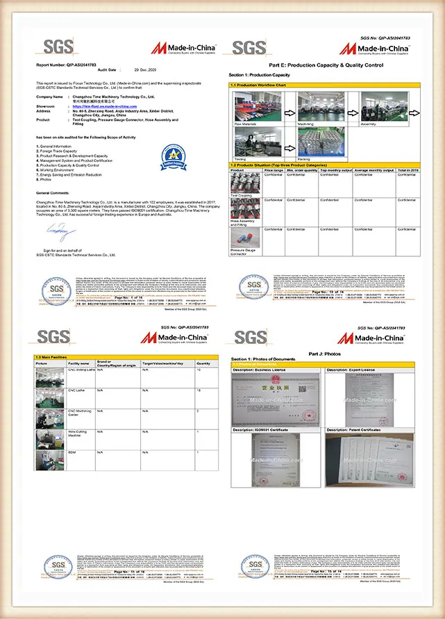
TIME Hydraulic operates a 5,000 m² production facility in China.
Define the audit or document scope if needed.
SYSTEM / SPECIFICATIONS
Quality Assurance: Production Control, Traceability and Warranty
Trust is easier to evaluate when the required evidence can be named before the order. Instead of a generic quality label, TIME Hydraulic ties drawings, traceability, material and inspection evidence to the written commercial scope.
01
Focused manufacturing
We specialize in and manufacture hydraulic test points and test hoses. This narrow scope keeps the conversation centered on diagnostic interfaces, hose routing and the documents needed for them.
02
Traceability
We maintain raw-material traceability for connector parts. State the required heat, batch, material or document linkage on the inquiry so the quotation can define the deliverable.
03
Warranty
These connectors carry a 3-year quality warranty. Ask for the applicable terms, claim process and model identity with the quotation rather than treating the duration as qualification evidence.
04
Company identity
IKIN is our registered trademark, and TIME Hydraulic is the operating company. TIME Hydraulic operates a 5,000 m² production facility in China.
05
Current development
New workshops are under development. This is a company-status fact; capacity, delivery or qualification outcomes are confirmed only in the relevant commercial and technical documents.
How We Work: From Gauge Specification to Approved Drawing
The fastest useful inquiry is not the one with the fewest fields. It is the one that separates known evidence from unknowns and gives both engineering and purchasing a shared revision to approve.
01
Record the job
Describe gauge location, diagnostic point, panel, operator access and whether a bulkhead route is preferred or merely being considered.
03
Review the evidence
Align pressure state, media, temperature, material, seal, inspection record and complete-chain boundary with the exact model.
02
Identify both sides
Send thread, seat, connection location, mating part number and clear photos or drawings for the gauge and diagnostic interfaces.
04
Freeze the revision
Approve part number, drawing revision, quantity, branding, documents and commercial terms before production scheduling.
STAGE .A
Engineering handoff
Keep the gauge drawing, panel sketch, diagnostic-side evidence and operating envelope in the same review pack. When one item changes, flag the affected interface instead of circulating an unlabeled screenshot.
STAGE .B
Purchasing handoff
Copy the approved part number and drawing revision into the inquiry, quotation and purchase order. List quantity, sample or trial stage, branding, evidence deliverables and destination as separate commercial fields.
STAGE .C
Receiving handoff
Check the delivered label and documents against the ordered revision before installation. Quarantine an unexplained mismatch and return it to the drawing owner; do not resolve it by comparing body shape alone.
DOCUMENTATION
Request a Current Product Drawing
Product Views and Model Evidence
These images are migrated from the legacy product page to preserve real product context on the new site. Use them for orientation, then request the current model drawing and evidence-index status before approval.
We support private-label and custom-logo orders subject to drawing and order review. Branding is released only after the approved connector configuration and artwork are linked to the order.
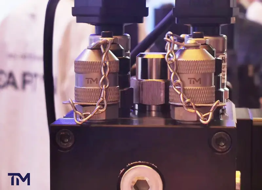
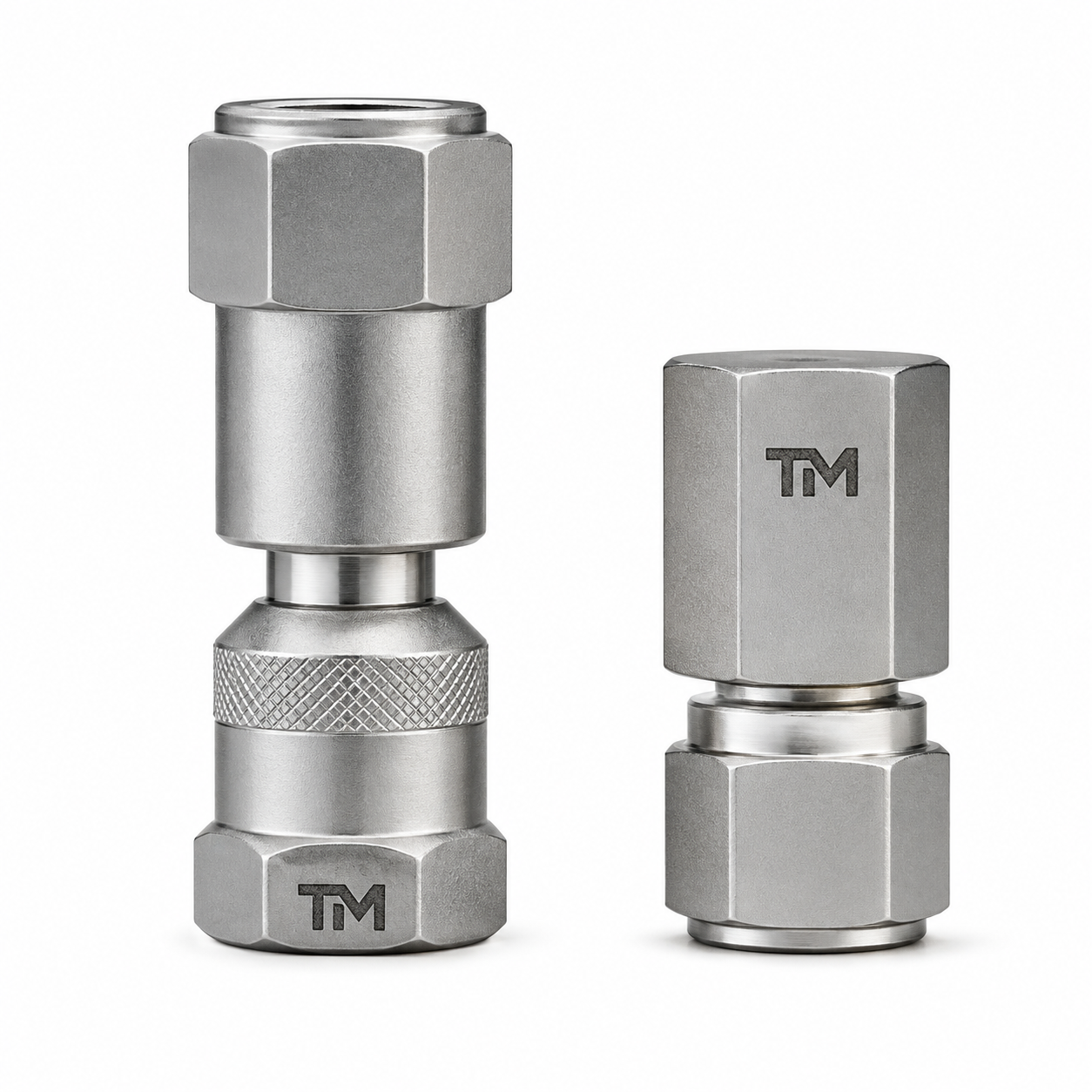
Bulkhead pressure gauge connector family view.
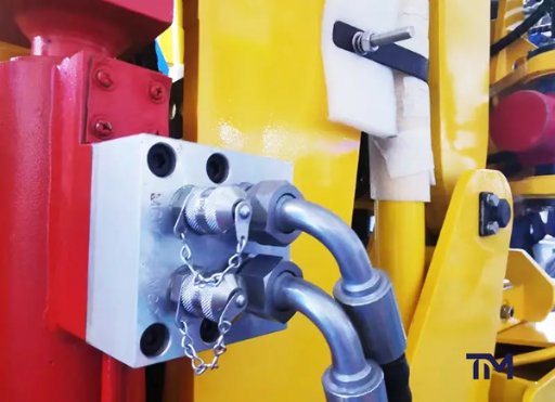
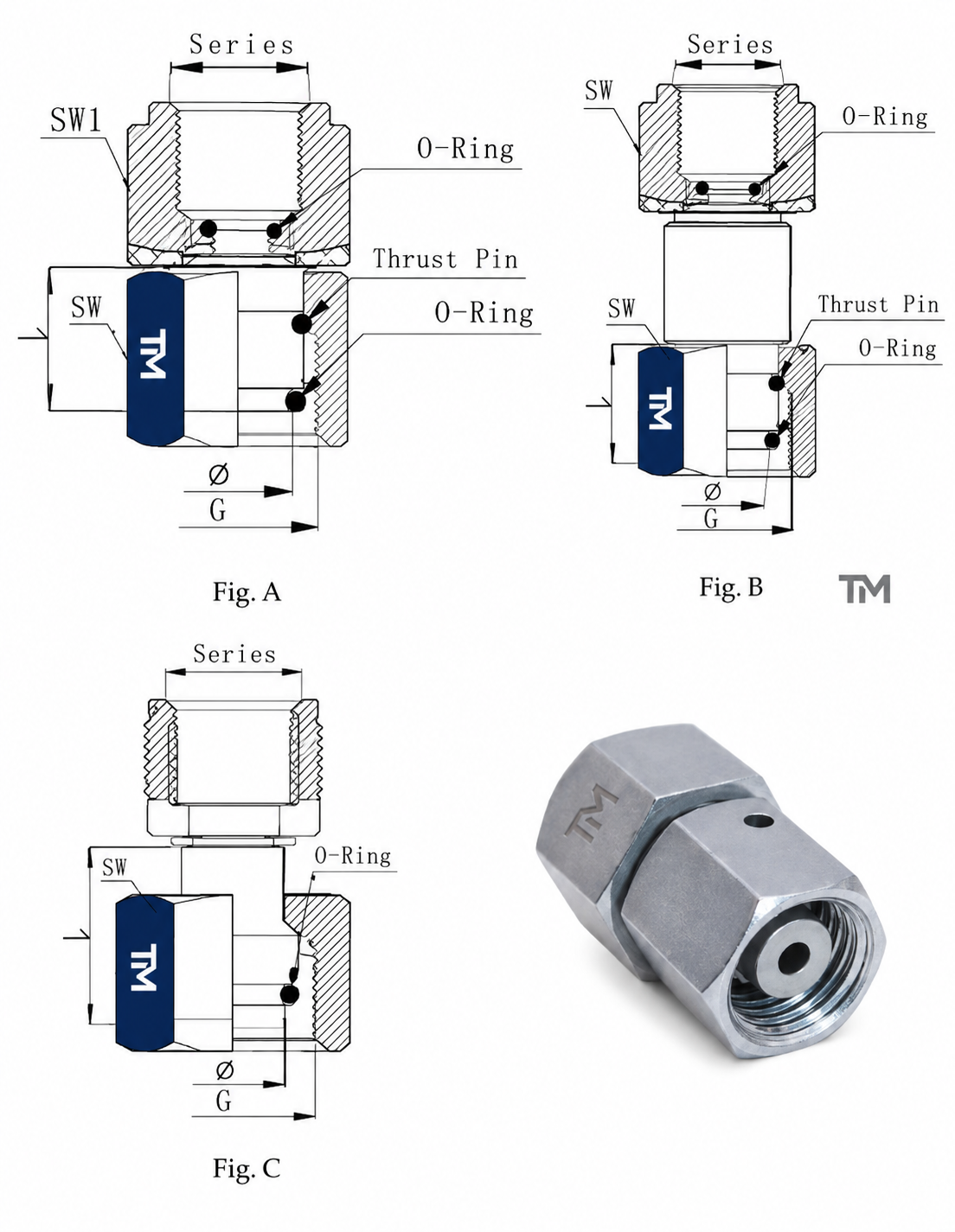
Legacy specification image for orientation only; current revision controls.
When a Bulkhead Gauge Connector Is Not the Right Choice
Rejecting the wrong architecture early is part of good selection. A direct adaptor or remote line may produce a cleaner, safer or more serviceable measurement route when the panel cannot support the intended job.


- Gauge can sit at the measurement point and remain accessible.
- Vibration, heat and clearance are acceptable at the port.
- Gauge orientation and removal path can be controlled.
- Both the gauge connection and process interface are documented.
- Separate the gauge from heat, vibration or poor access.
- Route the readout to a safer operator position.
- Protect and document the complete hose route.
- Validate every end connection and the complete-chain limits.
A bulkhead connector is not the automatic choice when the panel cannot safely support the gauge, provide locknut access or protect the measurement route.
Select the mounting architecture first; confirm panel geometry, vibration, heat, service access and complete-chain limits before drawing approval.
Next step
Request a Current Drawing and Quote
Send the gauge connection, diagnostic-side evidence, panel sketch, operating envelope, quantity and document requirements. TIME Hydraulic will review the selection record before binding a candidate model to a drawing and commercial offer.
Selection Guide
FAQ: Selection and Ordering
What is a bulkhead pressure gauge connector?
It is a through-panel connection that links a pressure gauge on one side of a panel to a diagnostic or system-side interface on the other. The exact model is defined by both interfaces and the mounting geometry.
Is a pressure gauge bulkhead connector the same as a general bulkhead fitting?
No. General bulkhead fittings often route tube or pipe through a panel, while this page focuses on a gauge-side connection and the diagnostic measurement job.
Can TIME select a model from a photograph?
A photograph can start the review, especially when it shows the connection location and surrounding panel. Final selection still needs measurable interface and drawing evidence.
Which gauge-side details should I send?
Send thread family and size, seat or sealing method, connection location, gauge case size, dial orientation and any existing gauge part number or drawing.
Which panel dimensions are needed?
Send hole diameter, panel thickness, accessible locknut side, nearby obstructions and required service clearance. Mark the preferred dial direction on the sketch.
Does a matching thread prove compatibility?
No. Seat geometry, sealing method, panel fit, diagnostic-side interface, material, media, temperature and pressure evidence remain separate decisions.
How should pressure suitability be reviewed?
Identify the exact model, pressure state, operating envelope, qualification method, acceptance criteria and complete-chain boundary. If those fields are incomplete, keep suitability under review.
When is a remote gauge line preferable?
Consider it when a direct or panel-mounted gauge would face poor access, vibration, heat, media-isolation needs or an unsafe viewing position. The hose route and complete-chain evidence then become part of the decision.
Are samples available?
Samples are available but are not always free; they usually ship within 3 days. The sample configuration and charge are confirmed after drawing review.
What is the custom-logo trial quantity?
Trial orders start at 100 pieces with a custom logo. Artwork, connector drawing and order details are reviewed before release.
How long do bulk orders take?
Bulk orders are scheduled for 10–30 working days, confirmed with your quotation. Timing begins from the agreed commercial and configuration milestone shown on the order.
What should I request with a quotation?
Request the current drawing, model evidence index, agreed material or seal evidence, inspection-record scope, warranty terms, quantity, payment term and Incoterm.
