
Get in touch with TIME Company

Hydraulic diagnostic connection selection
Test Point Adapters & Tee Connections
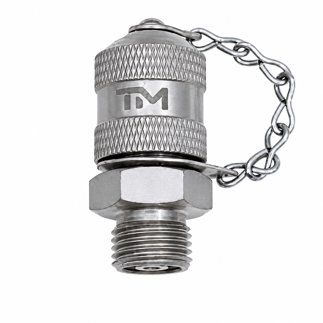
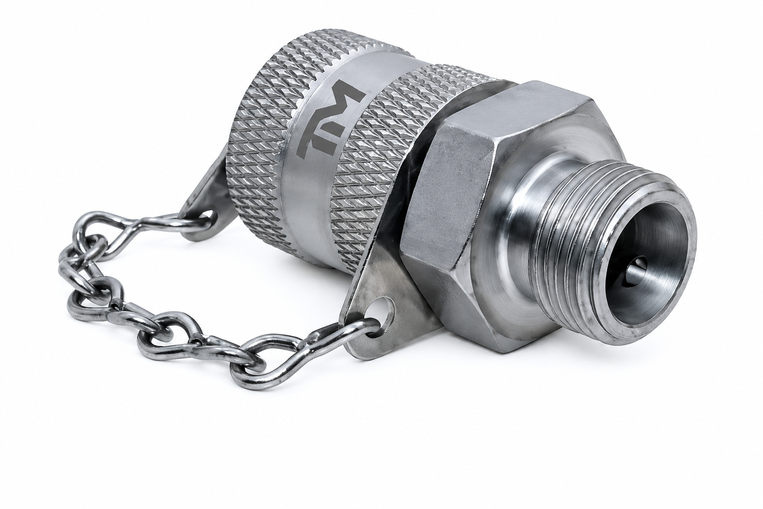
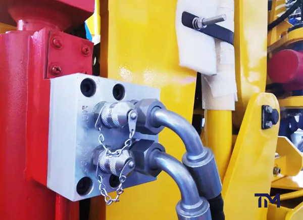
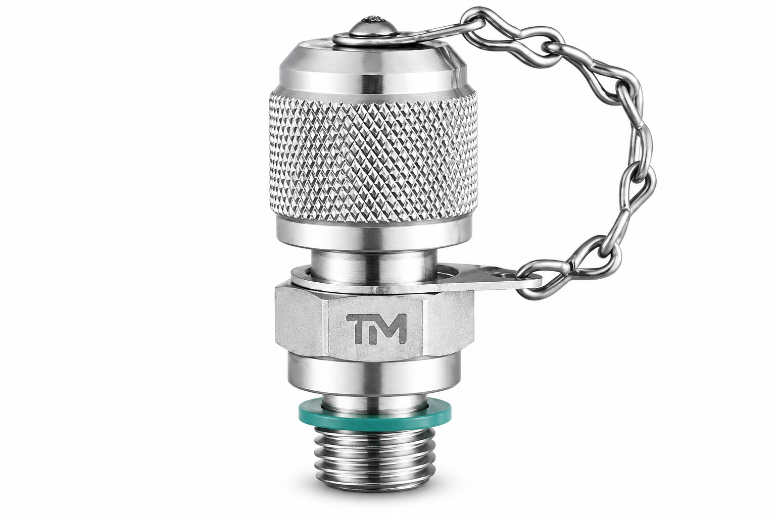
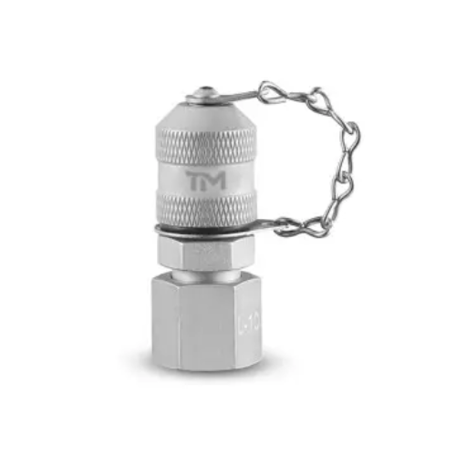
Define hydraulic test point adapters by the full connection stack—not by a thread label alone. TIME Hydraulic manufactures direct adapters and hydraulic test tee fittings to provide pressure-measurement or diagnostic access for troubleshooting, commissioning or planned inspections.
Start with five inputs
- Machine port or line connection standard
- Male/female state, seat and seal geometry
- Diagnostic interface and mating equipment
- Fluid, temperature and pressure-duty states
- Quantity, drawing revision and evidence scope
System side
Thread, seat, seal and tubeDiagnostic side
Interface, hose, gauge or sensorDuty states
Working, connecting and cyclingRelease evidence
Drawing, inspection and termsHydraulic Test Point Adapters at a Glance
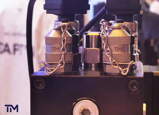
Direct hydraulic test port adapters use an existing port; inline tees create a diagnostic branch in a tube or hose run. The wrong route creates leak and rework hazards, so request a drawing review before the connection is released.
Existing diagnostic port
Direct path
Use an adapter when the machine already provides a suitable port and the required diagnostic interface can be introduced without changing the line path.
Tee test connection
Inline path
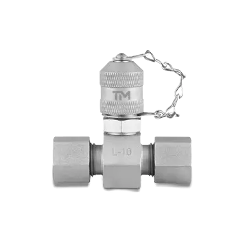
Use a hydraulic test tee fitting when pressure must be accessed from a line route and the tee geometry, orientation and added joints are acceptable.
Drawing-led selection
Review path
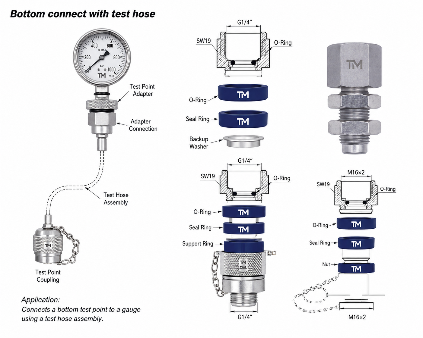
Use a current drawing when a product name or photo cannot establish the stud end, tube standard, seat, seal, envelope or mating interface.
Specification
Connection families
Review JIC 37°, ORFS, DKO 24°, cutting-ring, stud-end, gauge, tube and bulkhead routes as separate geometries.
Specification
Material and seal
Bind body material, finish and exact elastomer to the named fluid, temperature range and external exposure.
Specification
Evidence scope
Separate component working pressure from permitted connection state, dynamic duty and the lowest-rated element in the measurement chain.
Choose an Adapter or Tee by the Installation Path
The Adapter-or-Tee Routing Matrix displays the risk in choosing the wrong pathway because an existing port and an inline line branch produce distinct connection stacks. Request a drawing review to limit the options; the matrix alone does not approve an item for a machine or permit work on an energized system. ISO 15171-2 defines a scoped M16x2 diagnostic coupling path rather than a universal rule for choosing the system-side route.
Choose the condition that best matches the installation.
- I have an identified existing port
- I need to introduce a diagnostic branch in a line
- The connection path is not yet confirmed
Review requirements for direct adapter connection.
- An existing port appears on a current machine drawing.
- The system-side thread, seat and seal can be stated.
- The diagnostic end and tool clearance conform to the access boundary.
- An inline line branch is unnecessary for access.
Review requirements for inline tee implementation.
- The access point occurs along a tube or hose pipeline.
- Both extending line terminations and the diagnostic branch are defined.
- Tee orientation, wrench access and added-joint clearance are acceptable.
- The line intervention plan adheres to the machine procedure and site controls.
Connection Families for Test Point Adapters
Family names serve as routing designators, not interchangeability declarations. The current TIME drawing and the mating component must dictate the final choice. The ISO 15171-2 scope lists multiple stud-end paths, while SAE J1502 defines a separate diagnostic-coupler route with M14x1.5 or 9/16-18 stud ends, so neither standard makes an M16x2 diagnostic end the complete connection stack.
| Family | Identify on the system side | Do not infer | Useful request evidence |
|---|---|---|---|
| JIC 37° | Thread, 37° flare seat, male/female state and tube size | Another UN/UNF thread has the same seat | Port photo plus mating-part drawing |
| ORFS | Face-seal geometry, O-ring location, thread and dash size | Thread engagement alone establishes sealing | Face dimensions and O-ring specification |
| DKO 24° | 24° cone route, series, tube size and nut/sleeve arrangement | Every metric cone is the same standard path | Assembly drawing or measured connection stack |
| Cutting ring | Tube outside diameter, series, ring and cone geometry | Tube size alone selects the fitting | Tube and mating fitting designation |
| Stud end | Exact standard, thread, seal method and port counterbore | A thread name defines the sealing form | Port standard and dimensional section |
| Bulkhead | Panel thickness, retention, wrench access and both ends | Only the exposed thread matters | Panel section and installation envelope |
| Gauge adapter | Gauge thread, seal method, orientation and load support | Gauge range rates the adapter or hose | Gauge data sheet and mounting arrangement |
| Inline tee | Run-end standards, branch interface, orientation and flow path | A general hydraulic tee is a diagnostic tee | Line drawing and measurement-point purpose |
Terminology to Put on the Drawing
- Name NPT, NPTF or the applicable SAE designation instead of writing only “pipe thread,” then state the seat and seal.
- Separate test point fittings, the test coupling, a direct gauge adapter and the pressure gauge or hose in the measurement chain.
- State whether the task is a pressure test, system pressure monitoring or sampling; specify carbon steel, stainless steel, zinc nickel and the required resistance to corrosion only when the application and drawing require them.
- “Tee test connection” appears here solely in a hydraulic diagnostic application. Searching the phrase alone could pull medical results, so requests should specify the hydraulic connection family.
Materials, Seals and Corrosion Exposure
Material inconsistency causes leak and corrosion hazards because a generic “steel,” “stainless” or elastomer designator does not define compatibility. Request a detailed TIME material and seal review once the fluid, temperature and environment are defined. ISO 15171-2 scopes its coupling path to mineral-oil systems and calls for supplier-purchaser agreement for other fluids, so a thread label alone cannot close material and seal review.
Body material
State the required material condition and why it is needed: strength, corrosion exposure, fluid contact, cleaning regime or environmental restriction.
Surface protection
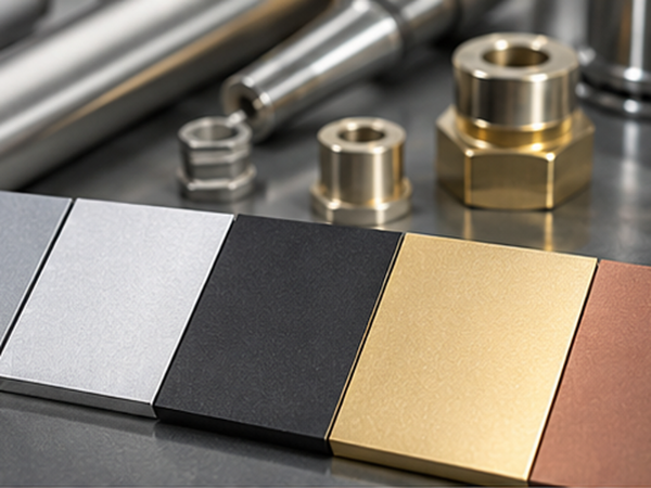
Define finish type, appearance limits and corrosion expectation on the quotation or drawing instead of assuming one treatment for every environment.
Exact elastomer
Name the seal compound, not only a family acronym, when fluid additives, thermal aging or regulatory constraints affect selection.
Hydraulic fluid
Provide the fluid family, product name or formulation context; “hydraulic oil” can be too broad for material review.
Temperature states
Include minimum start-up, continuous operating, peak and external radiant temperatures where relevant.
External exposure
Identify salt, washdown, fertilizer, mining dust, chemicals, outdoor storage or mixed-metal contact that may alter the material path.
Threads, Pressure States and Drawing Dimensions
The Connection Stack Verification Card transforms a thread-and-pressure risk assessment into an interface assessment because the two sets of data fail to identify the sealing configuration or intended duty. TIME hydraulic engineers use the official ISO 15171-2 scope as one evidence boundary—not as automatic product conformity—when reviewing a detailed drawing.
Working pressure
Steady-state limit for the stated component configuration.
Connection state
Whether connecting or disconnecting under pressure is permitted.
Dynamic duty
Transient peaks, impulse cycles, vibration and temperature effects.
Complete chain
Lowest applicable limit across adapter, hose, gauge, sensor and mating ends.
Engineering selection rule
Confirm against the current drawing because a working-pressure value is not interchangeable with connection-under-pressure permission, dynamic-life evidence or a complete-chain rating.
| Verification field | What to provide | Why it changes selection |
|---|---|---|
| Machine or line side | Exact standard and designation | Distinguishes thread from the full interface |
| Thread | Diameter, pitch and male/female state | Establishes engagement only |
| Seat or cone | Angle and dimensional reference | Identifies the primary sealing geometry |
| O-ring route | Face, boss or counterbore detail | Locates and supports the elastomer |
| Tube or hose | Outside diameter, series and end form | Routes cutting-ring, flare and hose families |
| Adapter or tee body | Geometry and orientation | Controls envelope and wrench access |
| Diagnostic interface | Standard, thread and mating connector | Links the component to hose, gauge or sensor |
| Working pressure | Required steady operating limit | Cannot stand in for connection permission |
| Connection state | Depressurized or applicable under-pressure scope | Separates operation from coupling action |
| Transient peak | Measured or design maximum | Can exceed the nominal operating value |
| Impulse/cycle duty | Cycle profile or qualification requirement | Changes fatigue evidence needs |
| Temperature | Fluid and ambient range | Affects seal and pressure capability |
| Fluid | Named family or product | Changes material and elastomer compatibility |
| Measurement chain | Hose, gauge, sensor and end connections | The lowest applicable rating governs the chain |
| Release evidence | Drawing revision, marking and inspection scope | Defines what the quotation and order control |
| Published or committed value | Controlled scope | Boundary |
|---|---|---|
| M16×2 | Diagnostic interface named by ISO 15171-2:2016 | Not the machine-side stud-end identity |
| 40 MPa maximum | Tool-free connection under pressure within the official ISO 15171-2 scope | Not a current TIME configuration rating |
| 63 MPa working pressure | Working-pressure scope stated by ISO 15171-2:2016 | Not dynamic-life or complete-chain evidence |
| 1 business day | Standard quotation response after sufficient inputs | Drawing review can require additional time |
| 10–30 business days | Prototype planning after specification confirmation | Final timing follows the quotation |
| 45–60 business days | Non-stock or custom production planning | Multi-part schedules are quotation-specific |
| 30% / 70% | Deposit and balance split | The written quotation controls the order |
| 3 years | TIME quality-warranty term | Written warranty terms define coverage and remedy |
Request completeness meter
- System-side standard, thread, seat and seal
- Adapter/tee geometry and access envelope
- Diagnostic interface and mating equipment
- Pressure, cycle, temperature and fluid duty
- Quantity, drawing revision and evidence scope
Quotation Inputs, Samples and Order Terms
Price depends on connection configuration, material, finish, seal, quantity, evidence scope and delivery schedule rather than a generic catalog price. Crisp requests avoid multiple interpretations before a purchase order is issued.
Request a Configuration-Specific Quote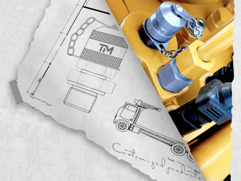
Order stage
TIME planning commitment
Scope boundary
Standard quotation
We return a standard quotation within one business day.
Starts after sufficient connection and quantity inputs are received.
Prototype planning
We plan prototype shipment in 10 to 30 business days after specification confirmation.
Final timing follows the confirmed configuration and quotation.
Non-stock or custom production
We schedule production in 45 to 60 business days. Multi-part orders require a quotation-specific schedule.
Applies after specifications and commercial terms are confirmed.
Minimum order
Minimum order quantities are 100 to 200 pieces per standard non-stock size and 500 to 1,000 pieces for custom fittings.
Trial quantities are confirmed with the quotation.
Evaluation samples
Evaluation samples can be arranged.
Sample charges, international courier freight and timing are confirmed with the quotation.
Payment
30% deposit and 70% balance before shipment.
The written quotation controls the order.
Delivery basis
We ship FOB Ningbo or Shanghai and EXW as standard; CIF and other Incoterms are available on request.
Named place and logistics details are confirmed in writing.
What moves the quotation
Connection family, part count, material, finish, seal, inspection object, packaging, sample path and delivery plan all influence the final quote.
What prevents rework
Current dimensional drawings, mating-connection photos, named fluid data and a complete pressure-duty statement reduce unresolved assumptions.
From Connection Data to a Released Drawing
The review boundary minimizes mismatch and rework because engineering identity and business identity remain together. Every handoff should reference the same connection stack as opposed to a loose family name.
Lowest-friction request package
- Current port or line drawing
- Clear connection photos with scale
- Mating hose, gauge or sensor data
- Fluid and temperature range
- Working, transient and connection-state requirements
- Quantity and required evidence
1
Send the connection
Provide the drawing, photo, standard designation or measured interface, plus the intended diagnostic task.
2
Close missing fields
TIME reviews thread, seat, seal, orientation, fluid, temperature and pressure-duty inputs.
3
Select the route
The request follows a direct adapter, inline tee or custom review path.
4
Confirm evidence
Drawing revision, marking, inspection scope and any configuration-specific verification are listed.
5
Quote one configuration
Commercial terms are tied to the selected material, seal, quantity and release basis.
6
Release and receive
The buyer reviews the drawing and written terms before order release and checks incoming parts against the agreed basis.
TIME Hydraulic Focuses on Test Points and Hoses
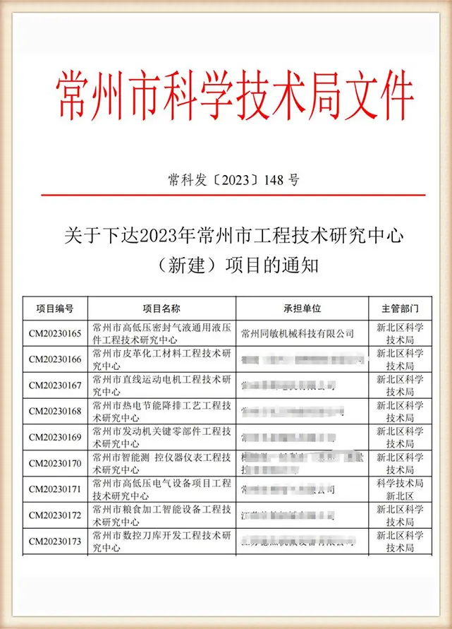
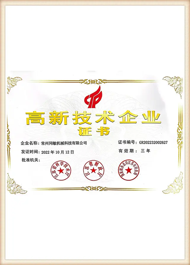
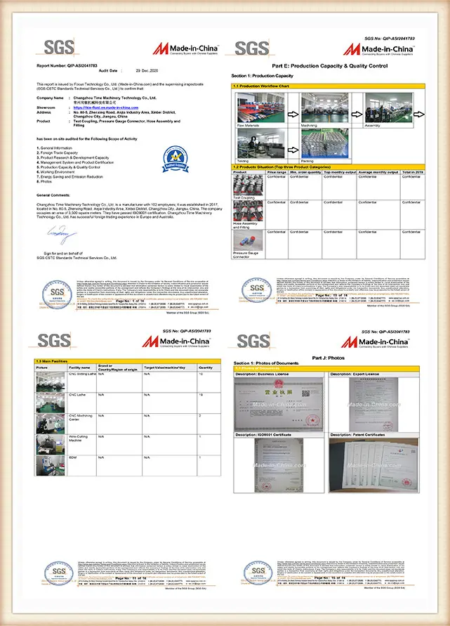
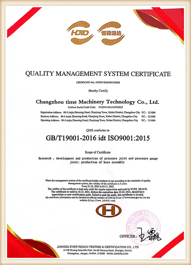
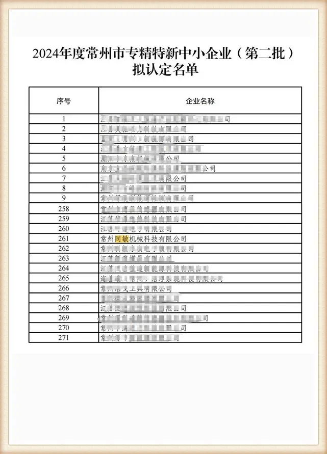
IKIN is the registered trademark and TIME Hydraulic is the operating company. TIME states that its factory focuses on hydraulic test points and hoses; its legacy site documents the adapter family and tee family, while 100% inspection and a three-year quality warranty remain defined through the ordered configuration and written terms.
Category 01
Focused product family
Adapter, tee, coupling, hose and gauge-connection requests can be reviewed as one diagnostic measurement chain.
Category 02
Cone-seal design claim
TIME describes its products as using a cone-seal, zero-leakage design; acceptance criteria and test conditions must be confirmed for the ordered configuration.
Category 03
Request-led support
Buyers can send drawings, connection photos and operating inputs for review before selecting a product path.
When a Catalog Adapter Is Not Enough
Contrary to a common assumption, a familiar thread is not necessarily the correct sealing interface. The trap is treating a catalogue value as decision-complete; confirm against the drawing and weigh the trade-off between a direct port and an added tee joint. Even the M16x2 diagnostic interface identified within ISO 15171-2 is not interchangeable with a verified system-side stud-end path, and a working-pressure value does nothing for connection-state approval.
- A correct thread with the wrong seat can still be the wrong connection.
- Adding a tee introduces orientation, envelope and additional-joint decisions.
- A catalogue pressure value may omit connection state and dynamic duty.
- A material name without the exact seal compound does not close compatibility.
- A quotation without drawing revision leaves interpretation risk.
| Condition | Why the simple route fails | Next action |
|---|---|---|
| Thread known; seat unknown | The part may engage but fail to seal on the intended geometry. | Provide a dimensional section or the mating-component standard. |
| M16x2 marked; standard path unknown | The diagnostic interface alone does not identify the stud end, fluid scope or connection-state permission. | Confirm both sides and the applicable standard/drawing. |
| One pressure value supplied | Working pressure may not cover connecting, transient peak, cycles, vibration or temperature. | Complete the four-boundary duty statement. |
| Direct port inaccessible | The correct interface may still lack safe tool, hose or wrench clearance. | Review orientation, extension, bulkhead or tee routes. |
| Line branch needed | A general tee may not carry the diagnostic interface or preserve the required run-end geometry. | Specify both run ends, branch and installation envelope. |
| Fluid or temperature unclear | Material and elastomer compatibility cannot be closed by a generic family label. | Name the fluid/product and temperature states. |
| Energized work proposed | Component capability does not authorize a maintenance activity. | Follow the applicable employer, machine and site hazardous-energy procedure. |
Pressure statement classifier
What does your current value describe?
Choose a pressure statement to see what it does—and does not—establish.
Engineering Tools & Selectors
Diagnostic route selector
Identify the correct diagnostic connection path based on your system threads, seating, and pressure duty standards.
Open Tool
RFQ completeness calculator
Verify your request parameters to eliminate interpretation loops and ensure accurate quotation of test adapters.
Open Tool
Pressure evidence map
Access compliance data, working pressure limits, and connection state ratings for your specific diagnostic assembly.
Open Tool
Selection questions
Hydraulic Test Point Adapter FAQs
These answers route a request toward the right evidence. They do not replace a current component drawing or a machine-specific service procedure.
Provide the exact system-side standard, thread, seat or seal, male/female state, diagnostic interface, fluid, temperature, pressure-duty states, mating equipment and quantity. A drawing or clear connection photo helps identify missing fields.
Use the tee review path when the measurement point is in a line and an inline diagnostic branch is acceptable. Specify both run ends, the branch, orientation, access and the line-intervention procedure.
It can appear as the diagnostic connection in standards and product families, but the label alone does not identify the machine-side stud end. Confirm both sides on the current drawing.
No interchangeability should be inferred from a similar diameter or thread. Their seats, seals, tube arrangements and standards must be matched to the mating connection.
They describe different actions and limits. ISO 15171-2:2016 is one example: its official scope states 63 MPa working pressure and a separate 40 MPa maximum for tool-free connection under pressure within that standard.
No. A standard explains a scoped interface and test path; TIME conformity must be supported by the exact current drawing and configuration evidence.
No. Review the adapter, mating connector, hose, gauge or sensor, end fittings, temperature and connection state; the lowest applicable limit governs the assembled chain.
Provide the named fluid, additives, temperature range, external exposure and applicable material restrictions. TIME can then review a configuration-specific material, finish and seal route.
Only when the applicable component standard, current product drawing and operating procedure explicitly permit that state. Component capability does not itself authorize work on energized equipment.
Connection geometry, material, finish, seal, quantity, sample plan, inspection object, documentation and delivery basis affect the final quotation. Send one controlled request package to reduce interpretation loops.
Evaluation samples can be arranged. Sample charges, international courier freight, timing and the sampled configuration are confirmed with the quotation.
Review the drawing revision, connection stack, material/seal route, pressure-duty statement, marking, inspection scope, quantity, lead time, payment and warranty terms. Keep that release basis available for receiving inspection.
