
Get in touch with TIME Company

Hydraulic pressure diagnostics
Tube Connection Test Points for Hydraulic Pressure Diagnostics
- DKO 24°
- Cutting-ring connections
- JIC 37°
- Drawing-led selection
Tube Connection Test Points provide a defined diagnostic connection on a hydraulic tube line for a suitable gauge, sensor, or sampling hose. TIME reviews the tube-side and diagnostic-side geometries separately, because a familiar thread does not define the complete connection.
Send whichever evidence is available: a drawing, part marking, tube-end photo, or installed-connection dimensions. An application review identifies any remaining gap before a model is selected.
The 24° / 37° Connection Verification Ladder
A defensible selection begins with physical connection evidence and ends with a released TIME drawing. The ladder prevents a male thread, brand nickname, or single pressure figure from deciding the whole assembly. A thread callout alone says nothing conclusive about the tube, seat, seal, or mating component.
Standard boundary
ISO 8434-1:2018 covers 24° cone connectors using cutting rings and O-ring seal cones identified as DKO. SAE J514-1_202606 covers 37° flared fittings, while ISO 15171-2:2016 addresses an M16 × 2 diagnostic coupling rather than the tube-side geometry. The mismatch risk persists because a standard defines a connection-family scope; it is not a substitute for the released drawing that fixes the TIME product and its acceptance criteria.
- Confirm the hydraulic context. Distinguish a tube connection test point from an electrical test point, pneumatic fitting, or general-purpose flare.
- Record tube size and series. Capture tube outside diameter, relevant wall data, and the light or heavy series before treating the nut thread as an identifier.
- Identify the sealing geometry. Separate a 24° DKO cone, a 24° cutting-ring assembly, and a 37° JIC flare by the seat and components that form the seal.
- Separate the two interfaces. The tube or machine side is one interface; the M16x2 diagnostic coupling, gauge adapter, hose, or coupler is another.
- Capture every component. Record the nut, cutting ring, O-ring, swivel, cap, thread sex, installed orientation, and any visible marking.
- Review pressure and medium. Keep working pressure, connection-under-pressure permission, fluid, temperature, material, qualification condition, and the complete test kit in separate fields.
- Release the decision. Match an existing configuration, request a missing dimension, or send the application for engineering review.
Three useful outputs
Identified
The connection family and required inputs agree with a current drawing. The quotation can name that drawing and revision.
Drawing required
The family is credible, but size, series, seat, or interface evidence is incomplete. The missing field is returned as a clear measurement request.
Application review required
Pressure state, fluid, temperature, live connection, or the measurement chain needs engineering confirmation. No visual guess becomes a safe operating decision.
DKO 24°, Cutting-Ring and JIC Connection Families
The error is to treat these names as interchangeable sales labels. TIME reviews the family, size, seat, and diagnostic side against one drawing instead of relying on a thread-only cross-reference. Compact labels such as “24°DKO” and “24°DIN” are family shorthand, not substitutes for drawing fields.
Thread is an input, not the answer
Wrong size or reversed male and female ends can turn a basic adapter order into another verification round. Equal thread and pitch do not establish equal tube series or seal geometry. That apparent match is not a substitute for a clear seat photo, tube measurement, and mating-part detail.
DKO 24° hydraulic test point
Geometry
24° cone with an O-ring seal cone in the ISO 8434-1 family.
Evidence
tube OD, series, thread, male or female side, cone form, and O-ring detail.
Drawing result
tube-side configuration plus the diagnostic interface and protection cap.
Hydraulic cutting ring test point
Geometry
24° cone connection assembled with the tube, nut, and cutting ring.
Evidence
tube OD, light or heavy series, nut thread, ring form, and installed orientation.
Drawing result
the complete compression connection, not a thread-only match.
JIC test point
Geometry
37° flared fitting family within the current SAE J514-1 scope.
Evidence
dash size or tube OD, UNF thread, flare seat, sex, and mating component.
Drawing result
a JIC 37° configuration without implying that a similar thread is compatible.
Tube connection hydraulic test point
Function
pressure monitoring, diagnostics, and application-approved sampling access.
Chain
tube side, test-point body and seal, diagnostic coupling, microbore hose, and gauge or sensor.
Selection
the lowest verified limit in the chain governs the setup.
Body Materials, Seals and Surface Options
We review carbon steel, 304 stainless steel, and 316L stainless steel against the fluid, environment, connection family, and required evidence. We also review NBR, FKM, and EPDM as seal-material options, with the compound and temperature range fixed on the applicable drawing rather than assumed from the family name.
Selection field
TIME options to review
Buyer input that controls the choice
Body material
Carbon steel, 304 stainless steel, 316L stainless steel
Fluid, corrosion exposure, temperature, maintenance interval, and material-document requirement
Seal material
NBR, FKM, EPDM
Fluid identity, concentration, operating temperature, cleaning exposure, and storage condition
Surface treatment
Zinc and Cr(VI)-free zinc-nickel
Base material, corrosion target, appearance, coating restrictions, and documentation
Sealing concept
Cone-seal design
Seat geometry, O-ring location, mating surface, torque or assembly requirement, and test condition
Port protection
Dust protection cap
Installed orientation, contamination exposure, service access, and cap retention preference
Identification
Custom marking and logo option
Marking text, drawing revision, quantity, packaging, and repeat-order code
Material is not a pressure shortcut
Connection geometry is checked against the applicable ISO 8434-1 family. A material upgrade is not a substitute for configuration-level evidence. The released configuration must keep body, seal, finish, fluid, temperature, connection state, and qualification evidence together.
Dimensions, Pressure Scope and Diagnostic-Side Fit
The selection table records what the drawing must settle before a hydraulic test port is released. It deliberately separates geometry, specification, pressure state, and evidence because each answers a different engineering question.
Selection field
Current decision rule
Release status
DKO geometry
24° O-ring seal cone; compare against ISO 8434-1:2018 scope
TIME model drawing required
Cutting-ring geometry
24° cone with tube, nut, ring, and L/S series evidence
Assembly drawing required
JIC geometry
37° flare; compare against SAE J514-1_202606 scope
Tube and mating-seat evidence required
Diagnostic interface
M16x2 (M16 × 2) is one diagnostic-coupling reference under ISO 15171-2:2016
Do not infer the tube-side thread
Tube size
Record outside diameter, wall data when relevant, and series before selecting the fitting
Measured value or drawing required
Pressure states
List working pressure, connection-under-pressure permission, proof condition, and complete-chain limit separately
Model and application approval required
Material package
Carbon steel, 304, or 316L body plus the specified seal and finish
Current material line on drawing required
Inspection
100% inspection before shipment
Inspection scope follows the order and drawing
Warranty
3-year quality warranty
Written warranty terms govern the supplied configuration
Sample service
Sample dispatch in 3 days; custom logo available.
Use the quotation to bind the selected item
The complete diagnostic chain
- Tube or machine connection
- Test-point body and seal
- Diagnostic connection
- Microbore hose or adapter
- Gauge, sensor, or monitor
Pressure evidence belongs to the row
Machine fitting and adapter family should be identified before the gauge, hose, and test fittings. Ask for the pressure basis, fluid, temperature, connection state, test condition, and drawing revision in the same line as the model. A headline rating is not a substitute for the weakest-component limit in an assembled diagnostic kit.
Use the selection tools
Connection Verification Ladder
Turn photos, tube data, thread, and seat evidence into an identified, drawing-required, or application-review state.
Open the verification toolTube Connection RFQ Builder
Assemble a complete request for a comparable drawing and quotation without leaving out the measurement chain.
Build the RFQ inputsPressure Scope Checker
Separate working pressure, live-connection permission, proof basis, and the complete-chain limit before review.
Check the pressure fieldsQuote Inputs and Sample Terms
Price follows the connection family, size, body and seal material, finish, quantity, marking, drawing work, and requested evidence. A comparable quotation starts with the same input set for every supplier.
Inputs that prevent a second clarification round
Input group
What to send
Why it changes the quotation
Tube connection
Tube OD, L/S series, thread, sex, cone or seat, nut, ring, and installed orientation
Defines the tube-side body and mating geometry
Diagnostic side
Coupling interface, hose end, gauge adapter, sensor, and required cap
Defines the measurement-chain connection
Application
Working pressure, live-connection requirement, fluid, temperature, and machine procedure
Controls material, seal, and engineering review
Commercial scope
Quantity, sample need, repeat-order forecast, logo, packing, and destination
Controls batch setup and service scope
Evidence
Drawing revision, material identification, inspection scope, marking, and warranty requirement
Defines the deliverables behind the part number
Inspection, Warranty and Product Evidence
We use raw material traceability and 100% inspection before shipment to keep the selected configuration tied to the order. A 3-year quality warranty supports the supplied product under its written terms.
Evidence follows the object
A management-system certificate, a material certificate, an inspection result, and a product drawing answer different questions. The procurement file should request the object that proves the release decision rather than a reassuring logo.
Request a Drawing-Based Application Review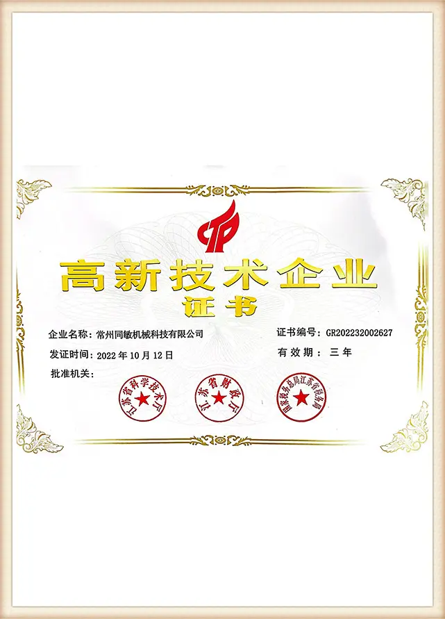
Evidence objects to request with the order
Controlled product drawing
Connection family, tube size, thread, seat, diagnostic side, material, seal, finish, and revision belong on one controlled object.
Inspection scope
Define the dimensions, visual checks, marking, and report format that must be accepted before shipment.
Material and finish identity
State which certificate, batch reference, or supplier record is needed instead of asking for a generic “quality document.”
Pressure evidence
Bind any pressure-test evidence to the model, test medium, condition, acceptance criterion, and report identity.
Warranty terms
Keep covered defect, notice route, evidence needed, and remedy in the written order record.
Repeat-order identity
Use part marking, drawing revision, and packing label so the next order does not depend on a photo or nickname.
How We Work: From Tube Data to Released Drawing
1
Send the connection evidence
Provide the tube data, installed dimensions, marking, drawing, or clear photos available.
2
Separate both interfaces
We identify the tube-side geometry and diagnostic-side requirement independently.
3
Review the application
Pressure state, medium, temperature, body, seal, finish, hose, and gauge enter the same review.
4
Close the missing fields
We match an existing configuration or return a focused dimension request.
5
Review the drawing and sample
The buyer confirms the applicable drawing, revision, marking, and evidence scope.
6
Release the written order
Quotation, inspection, packing, and shipment follow the agreed product identity.
Drawing notes that improve repeatability
Drawing field
Write this explicitly
Problem prevented
Connection family
DKO 24°, cutting-ring 24°, or JIC 37° plus the governing drawing reference
Nickname and angle confusion
Tube data
Outside diameter, series, wall or mating-part detail when relevant
Light/heavy series substitution
Seal
Seat form, O-ring location, compound, and mating surface
Thread-only selection
Diagnostic side
Coupling, hose-end, gauge-adapter, or sensor interface
M16x2 being mistaken for the tube-side connection
Pressure basis
Working, live connection, proof condition, fluid, temperature, and complete-chain limit
One rating being stretched across every state
Revision control
TIME code, drawing revision, marking, and approved substitution rule
Repeat-order drift
TIME Hydraulic Manufacturing Focus
As the manufacturer, TIME Hydraulic makes hydraulic test points and hoses under the IKIN product name in China. The company keeps its focus on the diagnostic connection rather than diluting the range across unrelated hydraulic components. TIME operates a 5,000 m² production facility and has new workshops under development.
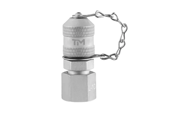
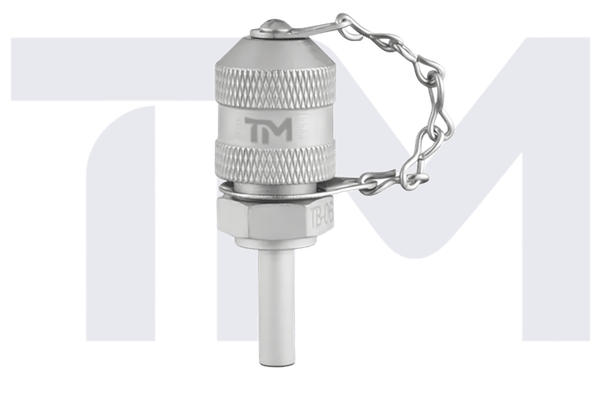
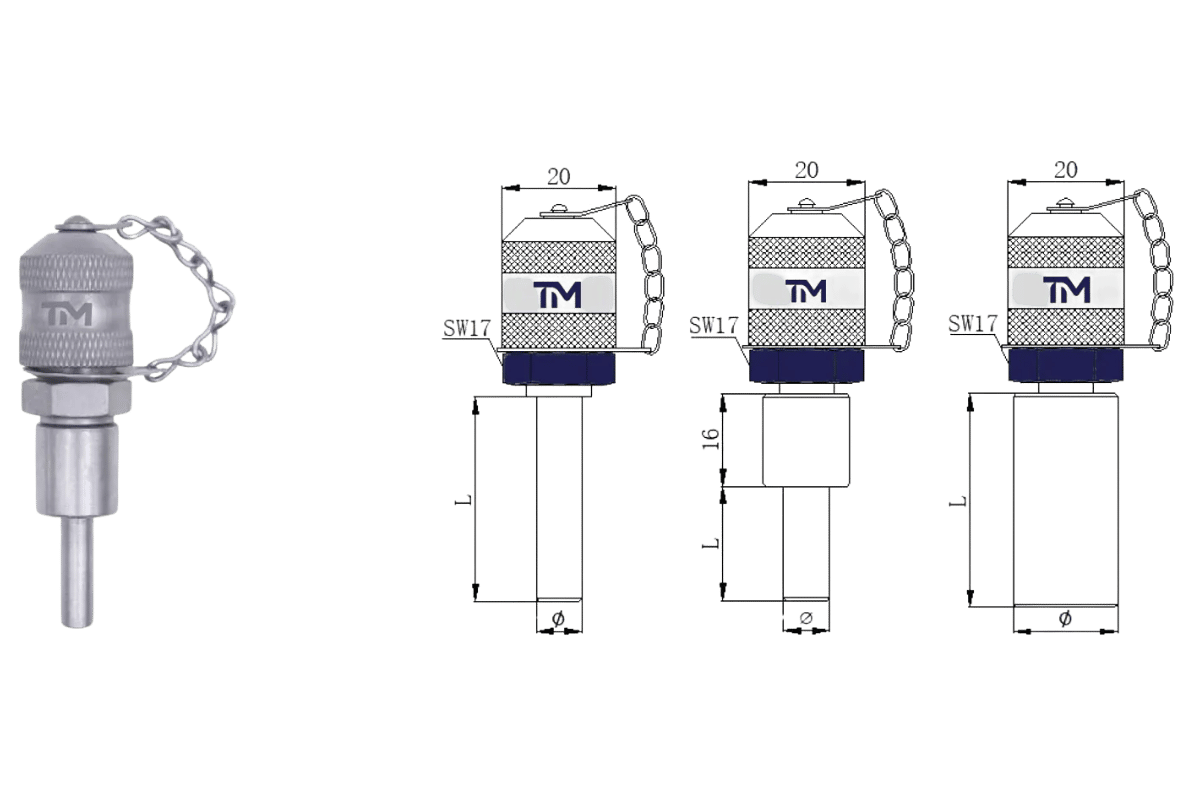
DKO 24° male-cone test-point product image from the TIME range.
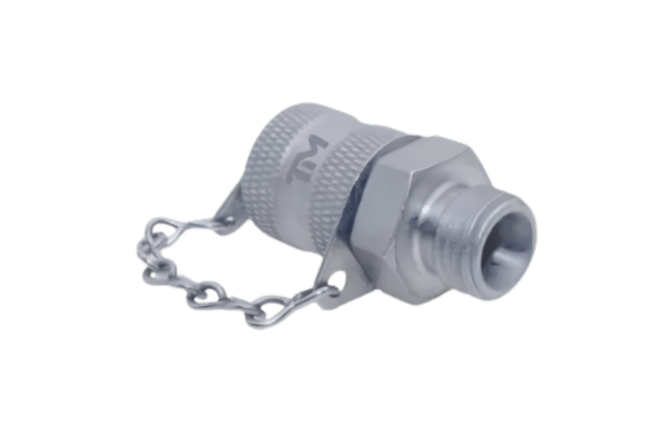
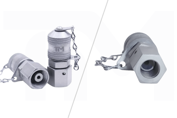
Cutting-ring tube-connection test coupling from the existing product family.
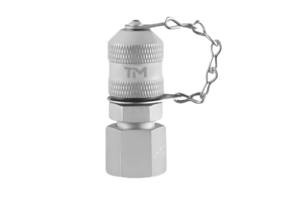
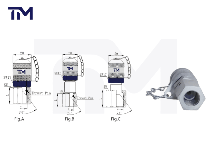
JIC 37° tube-side test coupling from the existing product family.
Selection Boundaries and Escalation Paths
A product page can narrow the family, but it cannot replace a machine-specific safety procedure or missing connection evidence. Each uncertainty below has a direct next action.
High-pressure fluid injection hazard
Do not search for an energized hydraulic leak with a hand or body part. Government pressure-test guidance requires control of hose and connector rupture or ejection hazards, and an OSHA record documents hydraulic fluid piercing a worker’s skin after a coupling leak; use verified equipment limits and the applicable employer energy-control and pressure-test procedure. Within its diagnostic-coupling scope, ISO 15171-2 also treats working pressure and connection-under-pressure as separate limits.
Request a Drawing-Based Application Review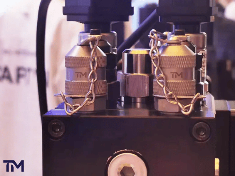
Unresolved condition
Why it blocks release
Next action
Cone or flare angle unknown
A 24° and 37° interface can share misleading visual features
Send a section drawing or measurable seat image
Tube OD or L/S series unknown
The same thread callout does not establish tube series
Measure the tube and capture nut or ring evidence
Thread known, seat unknown
The sealing interface remains unidentified
Record seat form, angle, sex, and mating component
Pressure, fluid, or temperature unknown
Body, seal, and safe connection state cannot be reviewed
Confirm machine data before model selection
Hose or gauge mismatch
The complete chain can be limited by another component
Review every adapter, hose, coupler, gauge, and sensor
Live connection not explicitly permitted
Working pressure does not prove connection-under-pressure permission
Follow the verified product limit and applicable machine procedure
Tube Connection Engineering Tools
Interactive Diagnostic & Verification Systems
Tube Connection Verification Ladder
Step-by-step verification to identify connection specifications without relying solely on thread size.
Open Tool
Tube Connection RFQ Builder
Assemble and validate a complete measurement chain request for accurate drawing and quotation matches.
Open Tool
Pressure Scope Checker
Analyze working pressure limits, live-connection permissions, and proof conditions across the diagnostic chain.
Open Tool
Request a Tube Connection Test-Point Drawing
For a hydraulic procurement review, send the information already available; we will identify missing fields during review. Tube Connection Test Points are selected more reliably when the connection evidence and complete measurement chain arrive together.
Request a Matching Drawing
Unsure of the connection family? Send an available drawing, part marking, or clear tube-end photo for review.
Required Procurement Inputs
- Company and contact
- Tube OD and series
- Thread and connection sex
- Cone, flare, seat, and seal
- Existing part marking
- Working pressure and live-connection need
- Fluid and temperature
- Hose, gauge, or sensor interface
- Quantity and sample need
- Drawing, photo, and evidence request
Tube Connection Test-Point FAQs
What information is needed to select a tube connection hydraulic test point?
Send tube OD, series, thread, seat or cone, sex, current marking, diagnostic-side requirement, pressure, fluid, temperature, quantity, and the clearest drawing or photo available. The output is an identified configuration, a dimension request, or an application review.
How is a DKO 24° hydraulic test point identified?
Confirm the 24° O-ring seal cone, tube and series evidence, thread, mating component, and diagnostic side. ISO 8434-1:2018 supplies the family vocabulary, while the applicable TIME drawing supplies the product identity.
How do cutting-ring and JIC 37° connections differ from DKO 24°?
A cutting-ring assembly uses the 24° cone family with a tube, nut, and cutting ring; DKO uses a 24° O-ring seal cone; JIC uses a 37° flare family. None should be selected from thread appearance alone.
Why are tube OD, series, thread, and seat all needed?
Each field identifies a different part of the connection. A matching thread can still leave the tube series, angle, sealing form, or mating component wrong.
How is the tube-side connection different from the diagnostic-side interface?
The tube side joins the test point to the hydraulic line or machine connection. The diagnostic side joins the test point to a coupling, microbore hose, gauge adapter, pressure gauge, sensor, or monitoring device.
How should working pressure and connection-under-pressure limits be checked?
Read them as separate fields on the current model drawing and include fluid, temperature, proof condition, and the complete chain. ISO 15171-2:2016 also separates diagnostic coupling working pressure from connection-under-pressure scope, which is why one figure should never cover both decisions.
Which body, seal, and surface options can be reviewed?
TIME reviews carbon steel, 304 and 316L stainless steel bodies; NBR, FKM and EPDM seals; and zinc or Cr(VI)-free zinc-nickel finishes. The drawing fixes the combination and any medium or temperature limit.
How is the test point matched to a hose and gauge or sensor?
Start at the diagnostic interface, then record every coupler, adapter, hose end, working-pressure limit, gauge range, and sensor connection. The lowest verified limit in the assembled path governs the diagnostic setup.
Can TIME review an existing drawing, part marking, or connection photo?
Yes. Send the drawing revision, readable marking, orthogonal photos, tube measurement, and mating-part details; TIME will identify what is sufficient and return only the missing fields.
Are TIME test points interchangeable with other brands?
Interchangeability requires agreement across geometry, dimensions, seal, diagnostic interface, material, pressure state, fluid, temperature, and qualification evidence. A brand cross-reference or familiar thread is not enough for release.
What sample, inspection, and warranty information can be requested?
Sample dispatch in 3 days; custom logo available. The order can also define the inspection scope, drawing revision, marking, product evidence, and the written terms of the 3-year quality warranty.
