
Get in touch with TIME Company

Hydraulic Test Point Products for Pressure Testing
Choose a hydraulic test point by the complete connection chain, not by thread diameter alone. A sound selection review looks at the machine-side port and sealing face, mounting form, diagnostic hose or gauge interface, service conditions, and material requirements before a model is set.
Your drawings and specifications are treated as confidential. Start the review with a stamped part number, drawing, or clear photograph with a ruler beside it.
Delivery & Quality Engineering Matrix
STATUS: ACTIVE
Quote turnaround
Within one business day
Prototype schedule
3 working days after drawing approval
Small-batch schedule
10 working days
Production schedule
10–30 working days, confirmed in quotation
Trial order
From 100 pieces with your own logo
Quality and warranty
100% inspection before packing, 3-year warranty
Hydraulic Test Point Product Families
Start with the installation geometry, then confirm both ends of the diagnostic connection used for pressure testing. These four families organize the TIME range around the buyer decision that usually changes the fitting, mounting method, or material. ISO 15171-2 defines one diagnostic-coupling interface; it does not establish that every family below falls within that standard.
01
Adapters & Tees
02
Stainless Steel
03
Bulkhead & Stud
04
Tube Connection
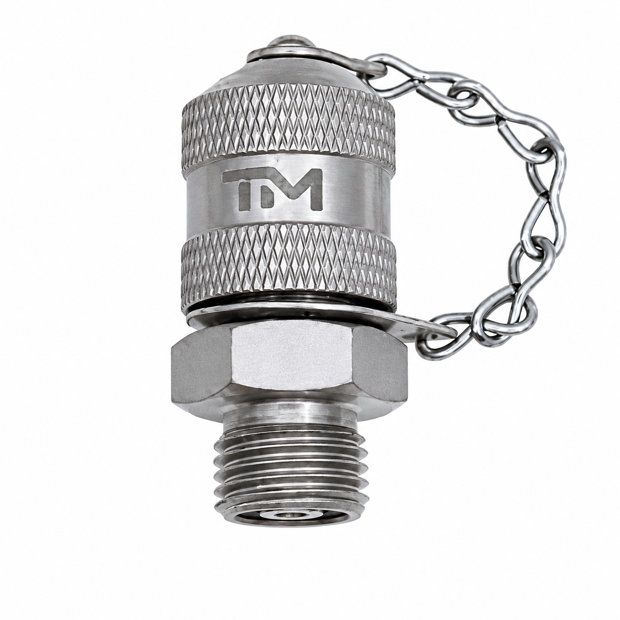
Test Point Adapters and Tee Connections
Choose this family when test access must be introduced through an adapter or branch connection.
Specifications
View adapter and tee options
- Existing Connections
- Branch Orientation
- Sealing Form
- Installation Clearance
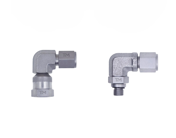
Stainless Steel Test Points
Choose this family when corrosion exposure, washdown, or fluid cleanliness makes material selection part of the specification.
Specifications
View stainless steel options
- Fluid
- Temperature
- Cleaning Chemistry
- Seal Compound
- Required Material Grade
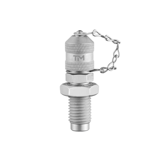
Bulkhead and Stud Test Points
Choose this family when the measurement access needs a fixed panel, bulkhead, or port-mounted position.
Specifications
View bulkhead and stud options
- Panel Thickness or Stud End
- Port Standard
- Sealing Face
- Access Direction
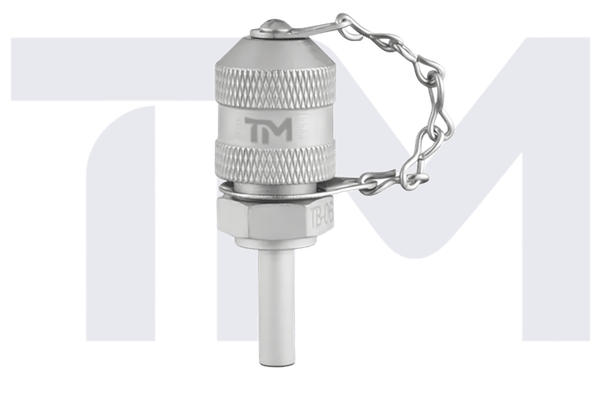
Tube Connection Test Points
Choose this family when the diagnostic point belongs in a tube connection rather than directly in a machine port.
Specifications
View tube connection options
- Tube Outside Diameter
- Connection System
- Mounting Position
- Available Wrench Clearance
Selection shortcut
If you only know the equipment model, include a clear photograph of the existing plug and sealing face. Previous repairs or inserts can make the as-found hydraulic port different from the manual.
Hydraulic Test Point Selection Factors
Each useful request for quotation defines the whole interface chain. These six fields route the request to a product family and show what still needs drawing-level confirmation.
Use this page for product-family comparison, connection options, specifications, and quotation scope. For machine-specific point placement, pressure-measurement or fluid-sampling routes, access, and safe-state planning, use the hydraulic diagnostic test point applications guide.
01 / PORT
Machine-Side Connection
Record the machine-side connection: thread family, diameter, pitch, taper or parallel form, and the sealing face. Thread engagement is not proof that the O-ring seat, cone, or bonded seal is correct.
02 / MOUNT
Mounting Form
Define the mounting form as direct, angled, bulkhead, stud, tee, or integrated with a tube connection. Include clearance around the cap and the direction in which a hose must approach.
03 / DIAG
Diagnostic-Side Interface
Identify what you need to measure and record the diagnostic-side interface: test hose, gauge adapter, sensor, or fluid-sampling connector. Send the mating part number or drawing when available.
04 / ISO
Connection Condition
State the connection condition, including whether the system is depressurized or the selected equipment specifically permits connection under pressure within the ISO 15171-2 scope. This is a model and procedure boundary, not a generic feature.
05 / COND
Service Conditions
Provide the service conditions: working pressure, expected pressure spikes, temperature range, hydraulic fluid, and gauge range. The highest printed pressure number is not a substitute for matching the real operating condition.
06 / SEAL
Material & Seal Environment
Describe the material and seal environment, including corrosion exposure, washdown, contamination-control needs, and fluid compatibility. Carbon steel, stainless steel, surface treatment, and seal compound are confirmed against that context.
01 / 03
Why the interface chain matters
Machine port, test point, hose or adapter, and pressure gauge are separate interfaces. Dimensional conformity at one connection does not prove the rated performance of the assembled diagnostic chain. Use these fields to resolve the connection sequence, while drawing inspection keeps an assumed thread match from becoming a product recommendation.
INTERFACE SELECTION PRINCIPLE
Confirm the sealing face and both sides of the diagnostic connection before using a nominal thread label to select the fitting.
TIME Test Point Product Finder
This finder routes a request to a product family; it does not select a precise model or declare compatibility. Final confirmation still requires the machine-side connection, diagnostic-side interface, and service conditions addressed by ISO 15171-2 where applicable, plus a current drawing.
Installation form
Not confirmed yet
Material driver
Standard industrial environment
Start with the interface checklist and send a drawing or clear port photo. This is a family route, not a model or pressure-rating confirmation. Keep the recommendation at family level.
-
ROUTE 01
Use the stainless steel route when material compatibility is the primary unresolved decision.
-
ROUTE 02
Use the adapter and tee route when an existing connection must be converted or branched.
-
ROUTE 03
Use the bulkhead and stud route for a fixed panel or direct machine-port installation.
-
ROUTE 04
Use the tube connection route when the access point belongs in the tube assembly.
Thread and Model Confirmation
Selection risk remains because ISO 15171-2 separates the M16 x 2 diagnostic coupling end, machine-side stud end, connection state, and reference fluid. TIME assigns the quoted rating from the current model drawing and service conditions.
01
Diagnostic coupling end
02
Connection under pressure
03
Maximum working pressure
04
Metric stud-end example
05
Metric stud-end alternative
06
Pipe-thread stud-end example
07
UNF stud-end example
08
Reference fluid
ISO 15171-2 scope
M16 x 2
What TIME still confirms
Current TIME model drawing and mating hose or gauge adapter
ISO 15171-2 scope
Up to 40 MPa (400 bar) within the standard scope
What TIME still confirms
Whether the selected model and maintenance procedure allow it
ISO 15171-2 scope
Up to 63 MPa (630 bar), conditional on material, design, conditions, and application
What TIME still confirms
Model-bound working limit for the actual service
ISO 15171-2 scope
M14 x 1.5 under ISO 6149-2
What TIME still confirms
Port geometry, sealing face, and drawing match
ISO 15171-2 scope
M14 x 1.5 under ISO 9974-2
What TIME still confirms
Correct standard and sealing arrangement
ISO 15171-2 scope
G 1/4 under ISO 1179-2
What TIME still confirms
Parallel-thread seal, port depth, and installation clearance
ISO 15171-2 scope
7/16-20 UNF under ISO 11926-2
What TIME still confirms
O-ring boss geometry and current port condition
ISO 15171-2 scope
Mineral oil; other fluids require supplier-purchaser agreement
What TIME still confirms
Fluid, temperature, seal compound, and material suitability
Pricing, Samples and Lead Times
Price follows the selected body form, material, seal, surface treatment, quantity, marking, inspection requirements, and delivery term. The price is provided in a written quotation after the interface and commercial scope are clear.
Supply stages
Quotation
Within 1 business day
Starts from a usable part number, drawing, or clear port photograph
Prototype
3 working days
Starts after drawing approval
Small batch
10 working days
Confirmed against quantity and configuration
Production
10–30 working days
Final schedule is confirmed in the quotation
Sample dispatch
Normally in 3 working days
Samples are available and normally dispatched. Sample charge depends on the selected item
Trial order
From 100 pieces
Own-logo marking can be included in the review
Payment and delivery terms
- We work on a 30% T/T deposit with the order and 70% T/T balance before delivery.
- We quote EXW, FOB, CIF and CFR, loading from Shanghai or Ningbo.
- FOB and sea-freight quotations can route from Shanghai or Ningbo.
- Quantity, destination, requested date, and marking requirements belong in the first RFQ.
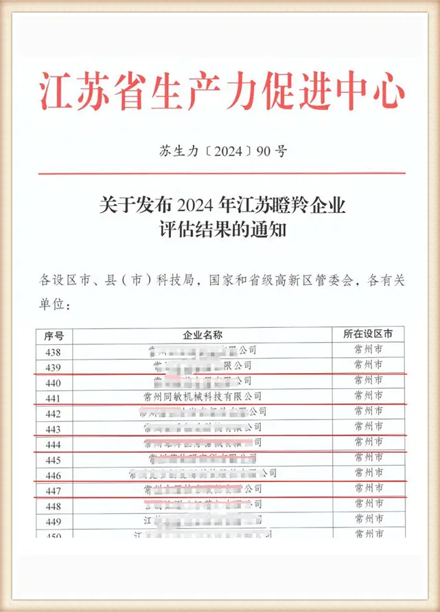
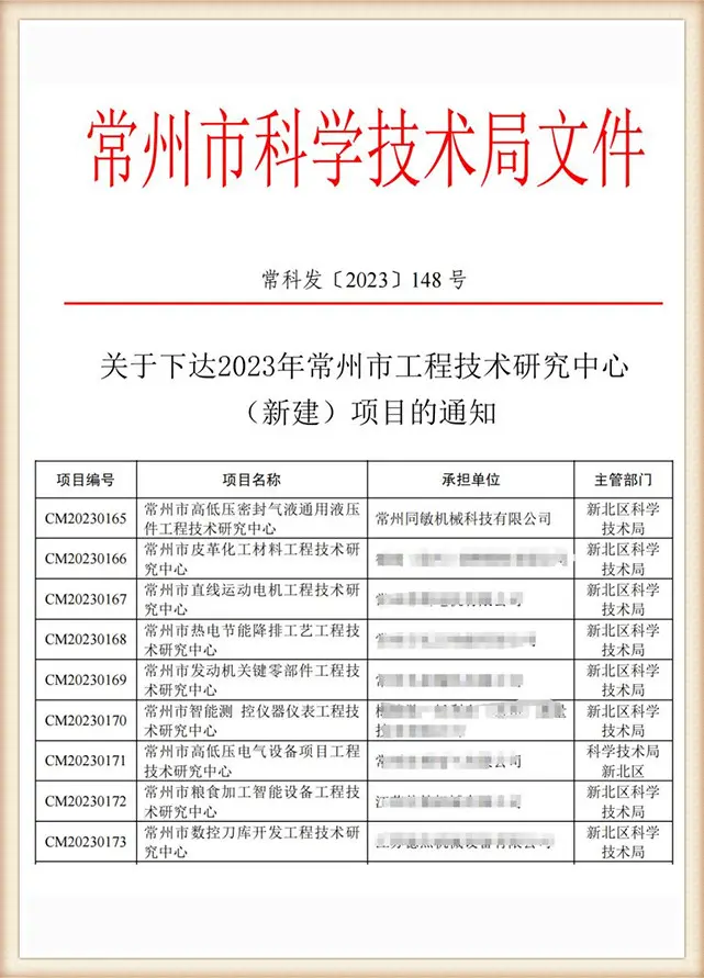
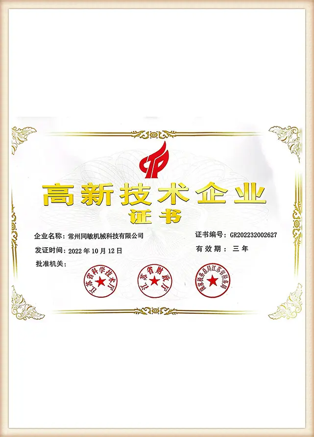
Quality Evidence and Supply Terms
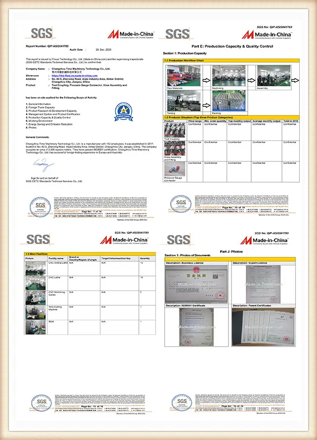
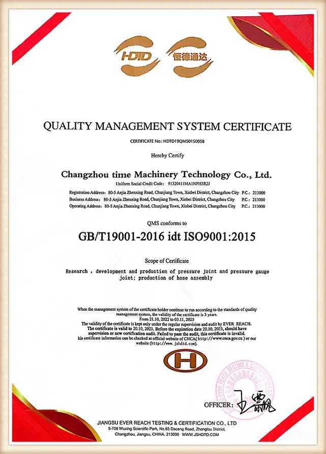
Every piece is inspected before packing, and material traceability can be maintained for the order. Acceptance still begins with an approved drawing, because a general product-family statement cannot replace the dimensions, material, seal, and rating assigned to the selected model.
Order controls
- The drawing review fixes the connection geometry, material, seal, marking, and inspection points before production.
- The prototype or first-piece check compares the initial part with the approved requirements before the order advances.
- An every-piece inspection covers 100% of parts before packing.
- Release and traceability match the packed order to the agreed identification and material records.
100%
Inspection before packing
3 years
Quality warranty
Drawing-led
Acceptance criteria
Traceable
Material records
Document confirmation
ISO 19879 describes testing methods for metallic tube connections; it does not by itself prove that a quoted TIME model has passed a particular test. Ask TIME to identify which current drawings, inspection records, test reports, and conformity documents are available for the quoted model. Material names and similar-looking test fittings do not establish a pressure rating or third-party approval.
Check the six RFQ inputs before requesting model documents
From Port Details to Approved Drawing
This finder routes a request to a product family; it does not select a precise model or declare compatibility. Final confirmation still requires the machine-side connection, diagnostic-side interface, and service conditions addressed by ISO 15171-2 where applicable, plus a current drawing.
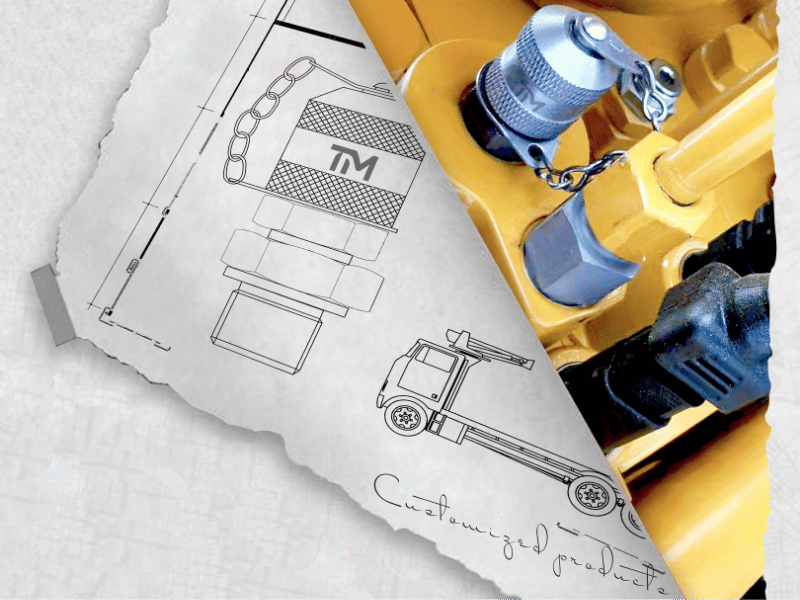
Send the available evidence by using a stamped part number, drawing, or a clear photograph with a ruler and a view of the sealing face.
Define both interfaces so the record covers the machine-side connection and the hose, gauge, sensor, or sampling connector on the diagnostic side.
Add service conditions such as working pressure under ISO 15171-2 where applicable, possible spikes, temperature, hydraulic fluid, connection state, and environmental exposure.
Review the family and material to identify unresolved drawing or compatibility questions before a precise model is discussed.
Approve the drawing and quotation after configuration, quantity, marking, schedule, payment, and delivery term are confirmed.
Inspect and release the order only after 100% inspection against the approved requirements before packing.
RFQ input checklist
Start with the interface checklist and send a drawing or clear port photo. This is a family route, not a model or pressure-rating confirmation. Keep the recommendation at family level.
Preferred evidence
Drawing or clear photo with dimensions
Decision it controls
Thread, pitch, sealing face, and mounting form
Preferred evidence
Hose, coupler, adapter, or gauge part number
Decision it controls
Mating interface and adapter chain
Preferred evidence
Normal value, peaks, and range
Decision it controls
Model rating and instrument range
Preferred evidence
Fluid name or specification
Decision it controls
Seal and material review
Preferred evidence
Corrosion, washdown, cleanliness, vibration
Decision it controls
Body material, surface treatment, and cap arrangement
Preferred evidence
Quantity, marking, target date, destination
Decision it controls
Price, production plan, and delivery term
Time Hydraulic Manufacturing Evidence
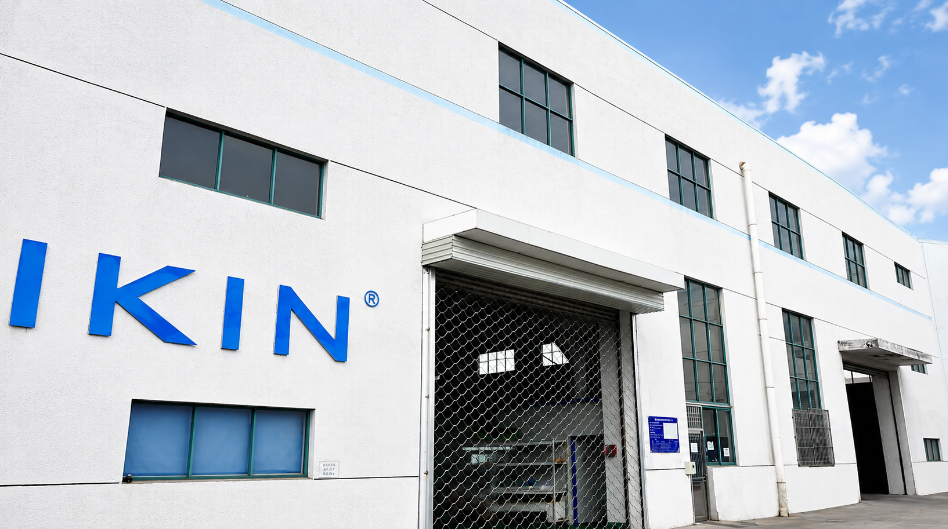
TIME Hydraulic operates from a 5,000 square metre site in Changzhou, built in 2017, with new workshops under development. The approved drawing and order documents should identify the required rating and conformity evidence for the selected model.
Drawing-led review
At quotation, a stamped part number, drawing, or clear photograph with a ruler helps resolve the interface.
Order-level inspection
Every piece is inspected before packing, with the approved order requirements providing the acceptance boundary.
Confidential engineering files
Drawings and specifications supplied for the project are treated as confidential throughout quotation and production.
Reference Evidence
Ask which supply references TIME is permitted to discuss for your application. A named reference does not imply partnership, endorsement, approved-supplier status, or compatibility with every model sold by that company.
Evidence to request with a quote
Ask for the current drawing, material and seal identification, model-bound pressure information with the ISO 15171-2 scope identified where relevant, inspection scope, and any required conformity document. That package is more useful than a broad brand-equivalence statement.
Configuration Trade-Offs
The most compact or highest-rated-looking option is not automatically the best hydraulic test point. Thread labels are not interchangeable with sealing geometry, and a material label is not a substitute for compatibility evidence.
01
Thread vs Sealing
02
Tee Addition
03
Hose Coupling
04
Material Selection
05
Cross-Reference
Situation
Thread diameter is known but the sealing face is not
Why it works against the selection
Similar nominal threads can use different pitch, taper, O-ring seats, or cone geometry.
Better route
Send the port drawing or a close photograph before selecting a model.
Situation
A tee is added only to avoid identifying the original port
Why it works against the selection
It creates more joints and still leaves the machine-side interface unresolved.
Better route
Confirm the existing connection first, then use an adapter or tee only when the branch is intentional.
Situation
The diagnostic hose uses a different coupling family
Why it works against the selection
A chain of unverified adapters can add leak paths and obscure the actual rating boundary.
Better route
Specify the hose or gauge connection with the test point in one interface review.
Situation
Stainless steel is selected without fluid and seal review
Why it works against the selection
Body material alone does not establish elastomer compatibility or performance at temperature.
Better route
Confirm fluid, temperature, cleaning chemistry, and seal compound together.
Situation
A cross-reference is requested by competitor part number only
Why it works against the selection
Matching catalog language does not prove dimensions, material, seal, or rated performance under ISO 15171-2 for an applicable diagnostic coupling.
Better route
Verify the two drawings model by model and record any difference in the quotation.
Hydraulic Test Point Tools
Interface Checklist
Open ChecklistPressure Unit Converter
Open ConverterRFQ Readiness Check
Open Readiness CheckHydraulic Test Point FAQs
Record the outside diameter, pitch, taper or parallel form, and sealing face. Add a clear photo because a 1/2-20 or M14 x 1.5 thread label alone does not show whether the port uses an O-ring seat, cone, bonded seal, or another geometry.
Yes. A similar diameter can engage while the pitch or sealing seat is wrong, so the connection may not seal or carry its intended load; TIME confirms the drawing and sealing geometry rather than using thread engagement as acceptance.
Only when the selected model and the equipment maintenance procedure expressly allow that connection state. ISO 15171-2 describes tool-free connection under pressure up to 40 MPa (400 bar) within its scope, but that number is not a universal TIME model rating or an operating instruction.
Provide the expected system pressure, possible spikes, and the circuit location. The gauge, test hose, adapter, and test coupling must each suit the measurement range; choosing from an assumed low-pressure circuit can damage the instrument or produce an unhelpful reading.
No. M16 x 2 can identify the diagnostic coupling end in ISO 15171-2, while the machine-side stud end may follow a different port standard and the off-machine hose connection must also be confirmed.
Include machine-side thread and sealing face, mounting form, diagnostic-side interface, working pressure and temperature, fluid, material or corrosion needs, quantity, marking, target date, and destination. A usable technical input supports the quote response within one business day.
A cross-reference request can be reviewed, but blanket interchangeability is not declared. Send the named part number and drawing so dimensions, seal, material, connection state, and rating can be compared one model at a time.
Use the stainless route when corrosion, washdown, cleanliness, or a specified material grade drives the project. Final suitability still depends on the hydraulic fluid, temperature, seal compound, cleaning chemistry, and current model drawing.
Samples normally dispatch in 3 working days, with the charge depending on the item. Prototype timing is 3 working days after drawing approval, and trial orders with your own logo start at 100 pieces.
Every piece receives 100% inspection before packing, and the quality warranty is 3 years. The approved drawing and written order define the accepted model, material, seal, marking, rating evidence, and inspection scope.
