
Get in touch with TIME Company

Valve-block diagnostics · drawing-led selection
Test Points for Valve Blocks & Hydraulic Systems
- Hydraulic test points & hoses only
- 100% inspection before packing
- 3-year quality warranty
TIME Hydraulic specializes exclusively in hydraulic test points and test hoses. We help engineering, maintenance and procurement teams select a hydraulic valve block test point by matching the block-side port, seal, pressure envelope, access space and diagnostic-side connection before a part is released.
Start with the diagnostic decision
A hydraulic valve block test point is one component of a measurement chain. Determine if the task will measure average steady-state pressure, capture a transient event, or support fluid sampling, then match the circuit, installed connection, test hose, and instrument.
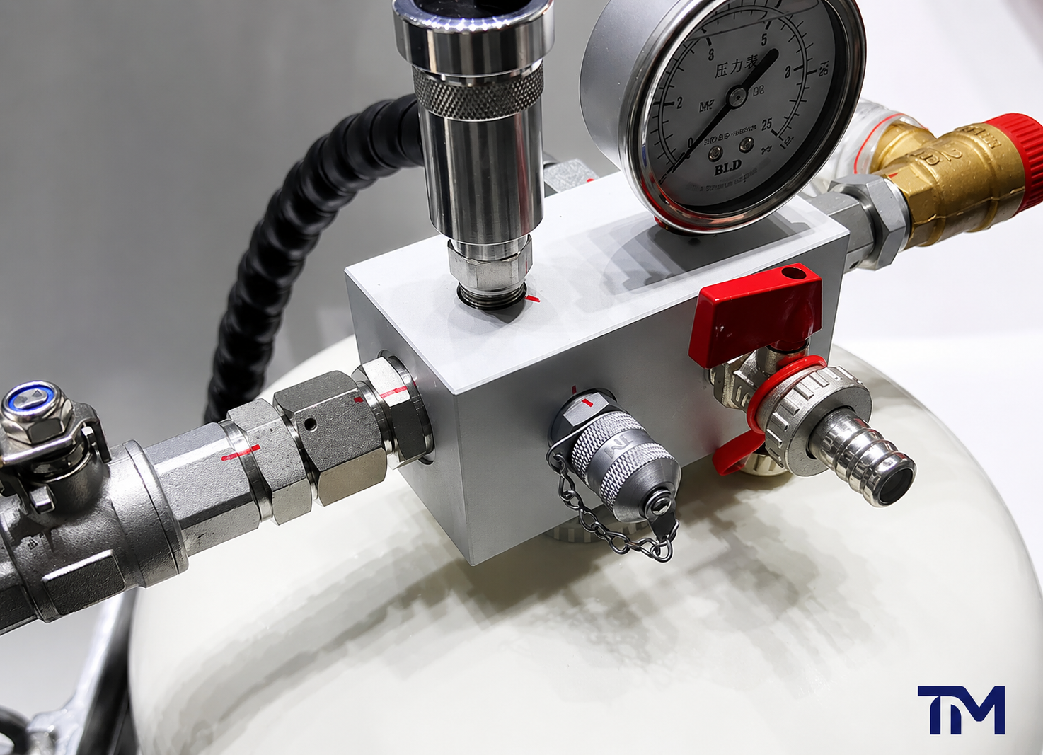
Average steady-state pressure, transient event or fluid sampling
Block-side thread, seat, counterbore and orientation
Working, connection, proof and burst pressure boundaries
Cap, probe, wrench and hose-routing clearance
Hydraulic Valve Block Test Points at a Glance
A test point can make pressure checks faster and more repeatable only when both interfaces and the service conditions are defined. The trade-off is a recordkeeping burden: a short part description still needs a complete drawing and service envelope. The cards summarize the selection scope; they are not universal specifications for every part number.
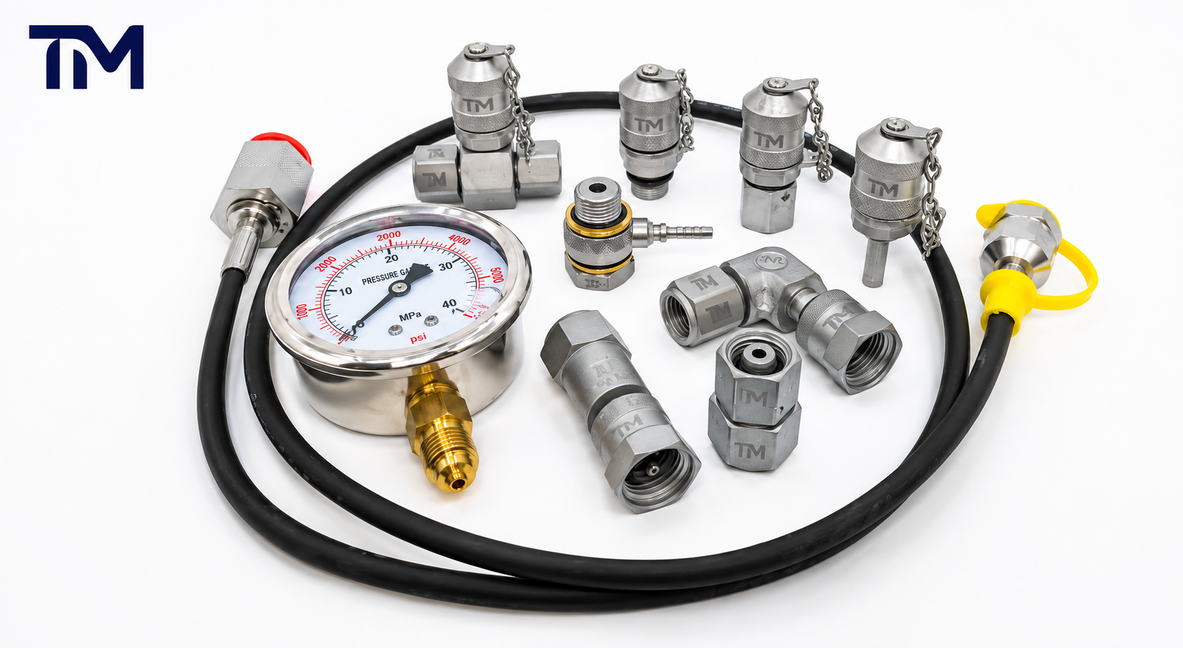
Connection range
The range includes bulkhead, stud, DKO 24° cone, ORFS, cutting-ring, JIC 37°, tee and tube connection families. Exact identity and dimensions remain drawing-controlled.
Documented metals
Documented configurations are available in DIN 1.0718 carbon steel, 304 stainless steel and 316L stainless steel. Material choice follows the fluid, external exposure and released configuration.
Documented seals
Documented configurations support NBR, FKM and EPDM seal options. The family name alone does not prove compatibility with a named fluid or temperature.
Seal architecture
Our range uses cone-seal, zero-leakage test-point designs. The applicable configuration and service envelope must still be confirmed on the current drawing.
Outgoing control
Every test point receives 100% inspection before packing. The requested inspection object and acceptance evidence should be stated in the quotation package.
Warranty and review
Products carry a 3-year quality warranty. Submit the existing port drawing or a clear photo so TIME can review an applicable configuration.
| Published review fact | Documented value | Boundary |
|---|---|---|
| Connection families | 8 listed families: bulkhead, stud, DKO 24° cone, ORFS, cutting-ring, JIC 37°, tee and tube | Part identity and dimensions remain drawing-controlled. |
| Metal designations | 3 documented options: DIN 1.0718 carbon steel, 304 stainless steel and 316L stainless steel | Applies only to listed part families. |
| Seal families | 3 documented options: NBR, FKM and EPDM | Actual compound compatibility remains application-specific. |
| TIME working-pressure statement | 630 bar maximum | Limited to the documented bulkhead, stud and stainless configurations. |
| ISO 15171-2 connection-under-pressure scope | 40 MPa (400 bar) | Standard scope, not a blanket TIME product or complete-chain rating. |
| Outgoing inspection | 100% before packing | The quotation should define the requested evidence object. |
| Quality warranty | 3 years | Bind the warranty to the ordered configuration and commercial record. |
The Valve Block Diagnostic Port Map
Use this map before choosing a manifold test point. Selecting on access alone is the wrong call; verify the diagnostic objective and circuit ID against the machine drawing or procedure, then record the geometry and complete measurement chain. For fluid-sampling decisions, apply the representative-sampling principles in ISO 4021.
What the map does: it converts a vague request for a hydraulic test port into a reviewable set of engineering inputs. It does not assign a universal port position or machine pressure.
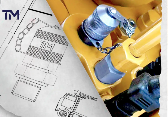
Pressure measurement, transient capture and oil sampling are different tasks
A static gauge check and a transient-event capture require different measurement-chain choices. A peer-reviewed study using water-filled pressure-transducer tubes found that tubing geometry, elasticity and trapped air can change dynamic response. It is useful as a measurement-chain warning, but it does not test hydraulic oil or establish any accuracy claim for a TIME hose.
| Circuit role | Decision the point should support | Inputs to verify | Escalation trigger |
|---|---|---|---|
| P / supply | Confirm available supply pressure, relief behavior or a pressure-loss question. | Machine schematic, expected steady range, transient objective, port geometry and access. | Do not infer pump condition from one reading without the specified test state and reference values. |
| T / return | Check return-side pressure or select a location for a defined maintenance task. | Allowable backpressure, filter position, sampling purpose, fluid cleanliness procedure and hose route. | A convenient return port is not automatically a representative oil-sampling point. |
| A / B work | Compare actuator-side pressure during a controlled operating step. | Valve state, load condition, expected direction, peak exposure, cap and probe clearance. | Work-port readings can change with load and valve state; record the exact test condition. |
| Load-sense | Evaluate the control signal within the machine maker’s diagnostic method. | Signal range, measurement uncertainty, sensor range, response requirement and safe access. | A general pressure gauge may not resolve the signal or transient behavior needed for the decision. |
| Pilot / control | Check command or pilot pressure at a named valve state. | Low-volume circuit behavior, hose volume, trapped air, sensor characteristics and procedure. | Added line volume can influence a dynamic measurement; validate the chain when timing matters. |
-
For a steady pressure decision
Record the operating state, expected range, gauge or sensor range, calibration status and acceptance threshold. Use the lowest applicable limit in the connected chain.
-
For a transient decision
Define bandwidth, sampling rate, hose or tube length and bore, purge condition, sensor mounting and uncertainty. Validate the assembled chain for the event of interest.
-
For representative fluid sampling
Select a location and cleanliness method that match the sampling objective. A pressure connection does not become a representative contamination-sampling port merely because it is accessible.
-
For energized-system access
Classify the activity and jurisdiction before work begins. Follow the employer’s hazardous-energy program, the machine procedure and the verified product boundary.
Connection Forms for Valve and Manifold Blocks
For selection support, review bulkhead and stud test points when the specified connection family matches the drawing and operating conditions.
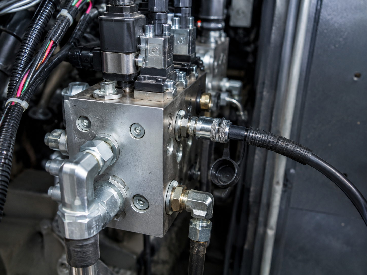
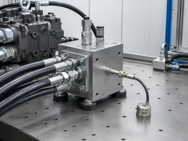
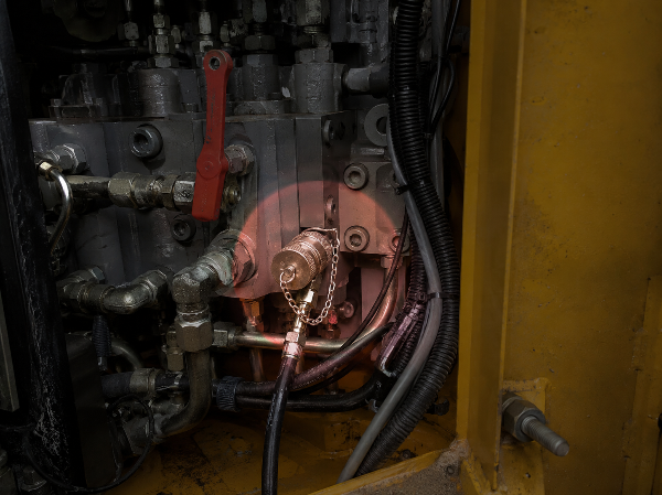
The valve-block connection and diagnostic coupling are separate interfaces; they are not interchangeable. A technically valid coupling can still fail the application if nearby valves or wiring block the cap, probe or hose. Identify the installed geometry and access envelope before TIME issues a drawing.
-
Bulkhead
Useful where the test point passes through a panel or bracket. Confirm panel thickness, nut access, orientation and clearance on both sides.
-
Stud
Installs into a threaded block port. Confirm thread, sealing method, spotface or counterbore and engagement on the released drawing.
-
DKO 24° cone
Pairs the test-point body with a documented 24-degree connection form. Do not treat the legacy stud-page wording as proof that every stud is DKO.
-
ORFS
Uses an O-ring face-seal connection form on the machine side. Verify dash size, face geometry, O-ring specification and wrench envelope.
-
Cutting-ring
Integrates with a tube and cutting-ring arrangement. Confirm tube outside diameter, series, material and assembly method.
-
JIC 37°
Uses a 37-degree flare connection form. Verify thread, flare size, material and whether the installation needs straight or oriented access.
-
Tee
Adds a diagnostic branch into an existing line connection. Confirm flow path, branch orientation, space and the effect on service access.
-
Tube
Places the test connection on a tube-based arrangement. Specify tube size, wall, material, pressure state and installation envelope.
Drawing control
Connection-family names help route a request; they do not replace dimensions. Send your current block or fitting drawing for a part-level match.
Send drawingMaterial strip
documented options include DIN 1.0718 carbon steel, 304 stainless steel and 316L stainless steel on documented configurations. Finish, coating, salt-spray duration and corrosion performance are not implied by the base-metal name.
Seal, Fluid and Corrosion-Exposure Selection
Choose the actual seal compound against the named fluid, concentration, temperature and exposure duration. A material-family label is not a substitute for application review; NBR, FKM and EPDM are option families, not universal compatibility approvals.
Selection input
What the buyer should provide
What TIME should confirm
Service fluid
Product name, base fluid, additives, concentration and contamination concerns.
Actual seal compound and wetted-metal compatibility for the proposed configuration.
Temperature
Normal, minimum and maximum temperature, plus exposure duration and cycling.
Configuration-bound seal, body and hose temperature limits.
External environment
Indoor, washdown, marine, salt, chemical splash, dust or weather exposure.
Material and finish choice; any applicable corrosion evidence and maintenance assumptions.
Maintenance method
Cleaning chemicals, purge method, cap practice and inspection interval.
Compatibility of seals, caps and finishes with the maintenance environment.
Non-mineral-oil agreement
ISO 15171-2 places use with fluids other than mineral oil under agreement between the supplier and purchaser. Provide the named fluid, concentration and temperature so compatibility can be reviewed against the proposed configuration.
Hold for application review
Hold for application review: water-glycol fluids, aggressive media, gases, unusual temperature, unknown additives or severe external corrosion. A family label such as FKM or stainless steel does not close the decision by itself.
Request ReviewPort Geometry, Pressure Scope and Diagnostic-Side Fit
A hydraulic system test connection includes at least two mechanical interfaces and one measurement path. Record each link separately so a correct thread designation does not mask a wrong seat, insufficient clearance, an incorrect pressure boundary or an incompatible instrument connection.
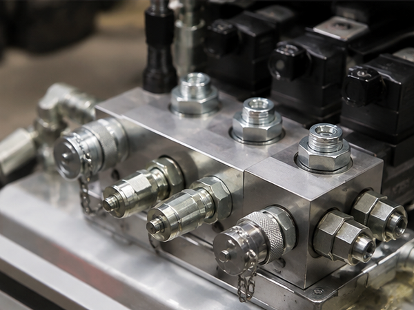
A thread name starts the match; the released section view completes it. A pressure number starts the rating review; the lowest applicable chain limit completes it.
Mismatch risk persists because a thread name does not define the seat or pressure state. TIME Hydraulic, operating under the IKIN trademark, resolves the selection with the released section view and configuration record; ISO scope remains separate from product evidence.
- Valve-block port
- Test-point body and seal
- Diagnostic coupling
- Test hose
- Gauge or sensor
- Decision
| RFQ field | Why it changes selection | Acceptable evidence |
|---|---|---|
| Circuit ID and objective | Defines what the reading or sample must answer. | Schematic reference, test step and acceptance criterion. |
| Machine-side thread | Thread system and size control engagement, but not the complete seal. | Dimensioned port drawing or verified measurements. |
| Seat or sealing form | A same-size thread can use a different sealing mechanism. | Section view, port standard and seal specification. |
| Counterbore or spotface | Controls shoulder seating, seal support and body clearance. | Diameter, depth, finish and adjacent geometry. |
| Orientation and access | Caps, probes and wrenches need space after installation. | Access envelope, assembly view or clear port photo. |
| Part working pressure | Limits the proposed TIME configuration during service. | Current TIME drawing or configuration-bound datasheet. |
| Connection under pressure | Is a separate state from normal working pressure. | Applicable interface standard, part drawing and machine procedure. |
| Proof and burst evidence | Uses different test methods and acceptance meanings. | Applicable test method, sample basis, result and configuration identity. |
| Complete-chain limit | The hose, adapter, gauge, sensor or procedure can be the lowest limit. | Ratings and procedures for every connected element. |
| Fluid, seal and temperature | Controls chemical and thermal suitability. | Named fluid, actual compound, range and exposure duration. |
| Diagnostic-side interface | Must match the probe or hose without being confused with the block port. | ISO M16x2 path or applicable SAE path on the drawing. |
| Hose and instrument ends | Control connection, range, routing and readable output. | End details, hose geometry, instrument range and calibration record. |
| Measurement uncertainty | A traceable instrument can still be unfit for the decision threshold. | Measurand, uncertainty budget, calibration chain and acceptance rule. |
| Sampling location | Pressure access does not prove sample representativeness. | Sampling purpose, flowline position, cleanliness method and procedure. |
| Revision and marking | Supports repeat orders and prevents drawing drift. | Released revision, part number and agreed marking. |
Quote Inputs, Samples and Production Terms
Procurement delays often begin with incomplete drawings or an undefined evidence package rather than the metal part. A comparable quotation needs both interfaces, material, seal, quantity, drawing status, sample requirement and evidence scope. Send those inputs together so the quotation and drawing review address one configuration.
| Commercial field | TIME commitment |
|---|---|
| Standard quotation | We return quotes within one business day for standard configurations. |
| Prototype timing | We ship prototype parts in 10 to 30 business days after specification confirmation. |
| Production timing | We schedule production runs in 45 to 60 business days for non-stock or custom production. |
| Minimum order | Our minimum order is 100 to 200 pieces per standard non-stock size and 500 to 1,000 pieces for custom fittings. |
| Samples | We supply standard evaluation samples without a sample charge, with international courier freight paid by the buyer; drawing-based samples quoted after review. |
| Payment | We accept 30% deposit and 70% balance before shipment. |
| Trade terms | We ship FOB Ningbo or Shanghai and EXW as standard; CIF and other Incoterms on request. |
Inspection, Drawings and Warranty
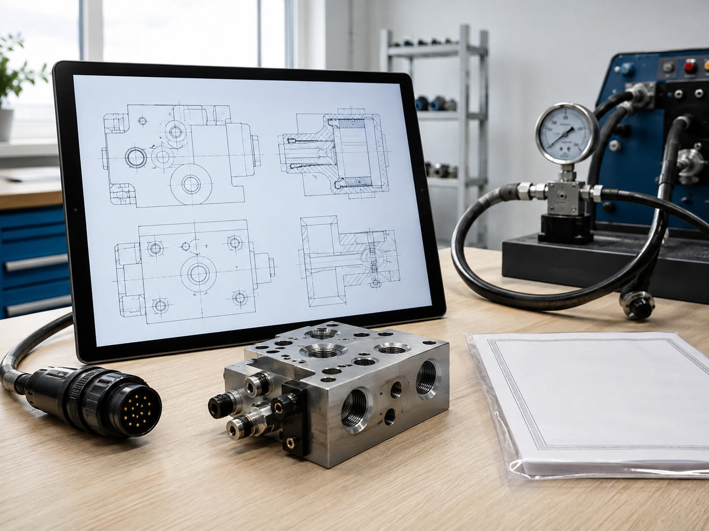
Fit, testing and performance evidence answer different questions. Agree the required records in the quotation so a dimensioned drawing is not mistaken for a test result or a management-system certificate.
-
01
Released drawing
Defines the part number, revision, dimensions, interfaces, material and configuration notes used for production.
-
02
Material and finish identity
Records the specified body material, seal family and finish for the ordered configuration.
-
03
Inspection scope
Defines what is checked, at what stage and against which acceptance points. Every test point receives 100% inspection before packing.
-
04
Performance qualification
Names the applicable method, sample basis, pressure state, acceptance criteria and configuration-bound result.
-
05
Part marking
Links the supplied item to the released identifier and supports repeat-order control.
-
06
Warranty
Products carry a 3-year quality warranty. Put the applicable warranty terms and ordered configuration on the commercial record.
Evidence Boundary
Request the Evidence Scope Checklist
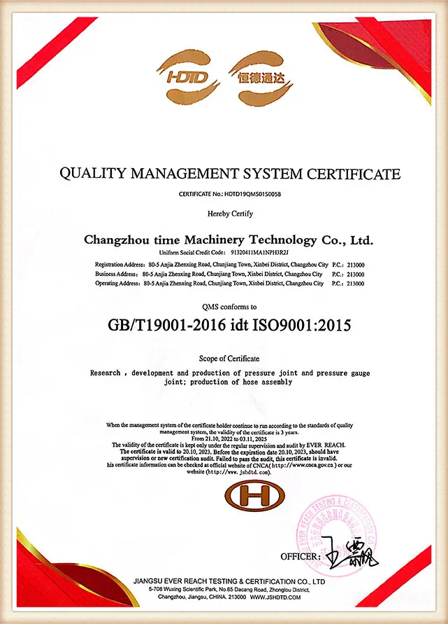
A quality-management-system certificate does not certify a specific product or guarantee its configuration performance. Use the released drawing, inspection scope and configuration-bound result for the ordered item.
Process
How We Work: From Valve-Block Data to Released Drawing
TIME keeps the buyer’s block data, proposed part and requested evidence in one review path. Each stage resolves a separate fit, performance or purchasing ambiguity.
STEP 01
Submit block and circuit data
Send the circuit ID, diagnostic purpose, existing port drawing or photo and the operating envelope.
STEP 02
Check geometry and access
TIME reviews thread, seal or seat, counterbore, orientation, cap clearance, probe access and hose routing.
STEP 03
Match the service envelope
TIME checks pressure states, fluid, actual seal requirement, temperature, material and external exposure.
STEP 04
Identify the configuration
TIME identifies an existing option or a drawing-based configuration and defines the diagnostic-side interface.
STEP 05
Review drawing and evidence scope
The buyer reviews the drawing, requested inspection objects and any applicable sample evaluation before release.
STEP 06
Produce, inspect and ship
Production, 100% inspection before packing and shipment follow the written quotation and released configuration.
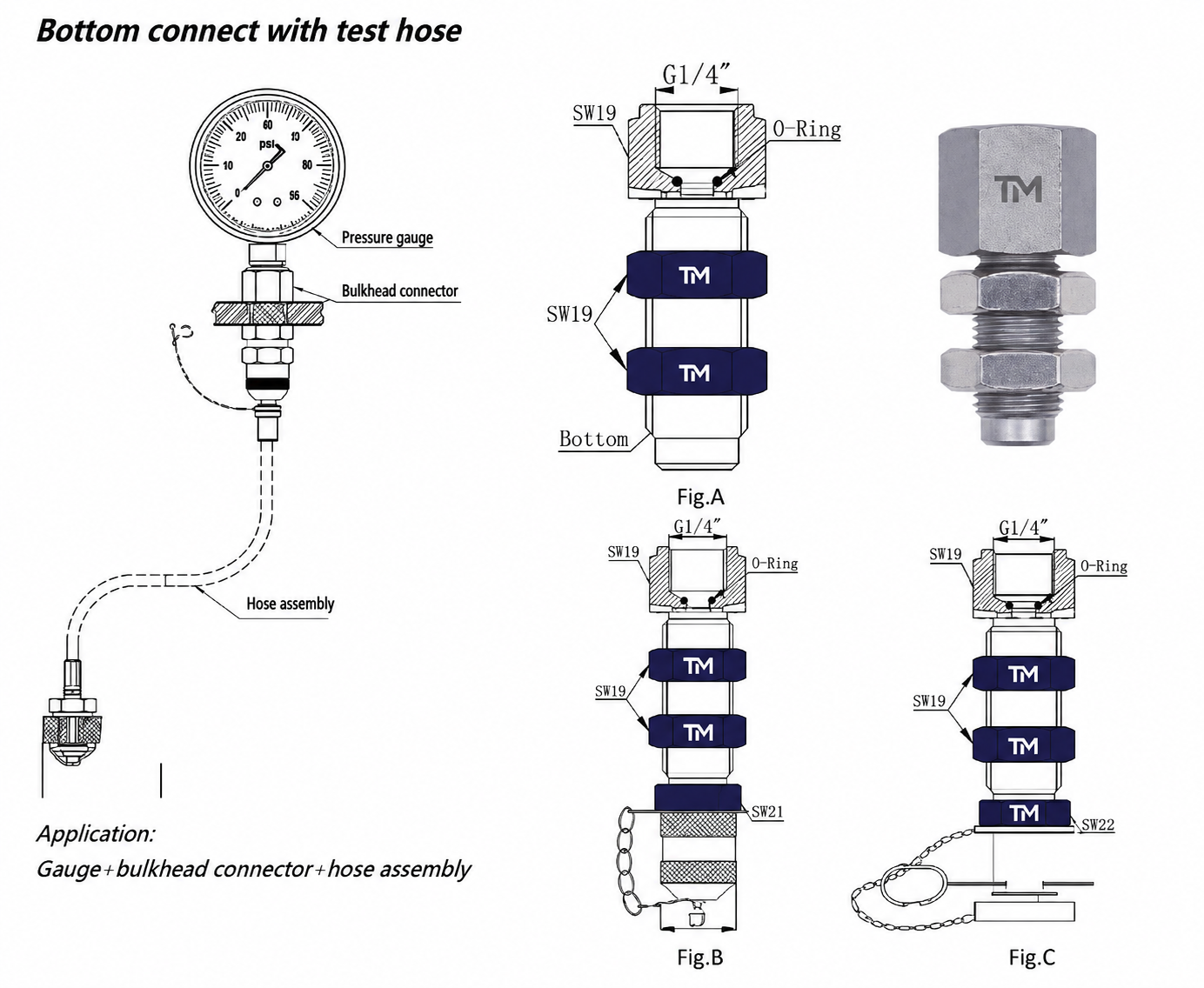
Parts We Manufacture: TIME Hydraulic Focus
IKIN is the registered trademark; TIME Hydraulic is the operating company. The company focuses on hydraulic test points and test hoses rather than a broad catalogue of unrelated hydraulic components.
01 / SPEC
Focused product family
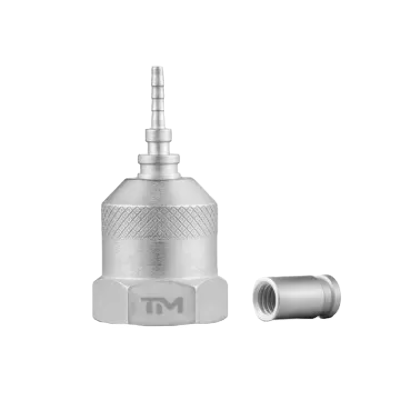
Specialization supports repeatable system monitoring and testing plans for port geometry, test couplings, microbore hose assemblies and measurement access.
02 / CAPA
Production footprint
Production is based in a 5,000 m² production facility, with new workshops under development. The figure is stated from the current client brief.
03 / PROC
Drawing-led supply
TIME can review existing valve-block data and route the request to a documented or drawing-based configuration.
Policy / Validation
Page proof policy: real product, factory or inspection media may be added only when ownership and subject are confirmed. Generated imagery is not used as evidence of products, facilities, certifications or customer applications.
Selection Boundaries and Escalation Paths
A useful guide marks where catalogue matching ends. Follow the action for each unresolved condition before accepting a part number or connection procedure. Where connection qualification is in scope, apply ISO 19879 only with the component-specific test method and acceptance criteria.
| Step | Unresolved Condition | Required Action & Boundary |
|---|---|---|
| Condition 01 | Thread or seat unknown |
Submit a dimensioned port drawing or clear measurements. Do not identify the connection from nominal diameter alone. |
| Condition 02 | Counterbore unresolved |
Request a port-section review with diameter, depth, spotface and adjacent clearance. |
| Condition 03 | Pressure or fluid unknown |
Confirm each pressure state, named fluid, actual seal need and temperature before selection. |
| Condition 04 | Cap or probe access blocked |
Provide the installed access envelope or a clear photo showing nearby valves, wiring and structure. |
| Condition 05 | Gas or aggressive media |
Request application review with media composition, temperature, exposure and leakage requirements. |
| Condition 06 | Pressurized connection not explicit |
Follow the verified interface limit, the current product drawing and the machine procedure. Working pressure alone does not grant permission. |
| Condition 07 | Transient accuracy required |
Validate hose geometry, purge state, sensor response, acquisition rate, calibration and uncertainty for the event. Use NIST metrological traceability guidance to define the measurement-result boundary. |
| Condition 08 | Energized-system exposure |
Apply the employer's hazardous-energy program and jurisdiction-specific requirements. Address stored, residual and reaccumulating energy before access under the applicable hazardous-energy program, such as OSHA 29 CFR 1910.147 for covered general-industry work. |
Diagnostic & Engineering Tools
Valve Block Port Selector
Identify and select correct port specifications for valve block integration. Ensure precise compatibility with standard testing interfaces.
Open Tool
Pressure Chain Limit Checker
Calculate and verify maximum pressure limits across your diagnostic chain. Prevent overload and maintain system safety margins.
Open Tool
Port To Evidence RFQ Builder
Generate a comprehensive request for quotation based on port geometry and service conditions. Streamline your technical procurement.
Open Tool
Hydraulic Valve Block Test-Point FAQs
Selection risk: use these answers to identify the drawing, service and commercial facts that still need review.
For the first review, combine the circuit identifier and diagnostic decision with the machine-side thread, seat or seal, counterbore, orientation, nearby clearance, working and connection pressure states, named fluid, temperature, test-side interface, hose or instrument end, order quantity, evidence request and revision of the existing drawing, because each field can change either selection, validation or quotation scope.
Supply, return, work, load-sense and pilot or control circuits can include planned diagnostic access when the machine design and procedure permit it. Verify the location, expected range and test condition in the machine schematic.
The machine-side port joins the test-point body to the valve block and includes its own thread, seat or seal and cavity geometry. M16x2 can describe the diagnostic coupling interface used by the probe or hose, so the two sides must be listed separately.
Include thread designation and class, engagement, seat angle or seal method, counterbore or spotface diameter and depth, surface requirements, orientation and nearby clearance. Add the diagnostic-side interface and cap envelope to the same drawing.
Engineering summary: fit requires thread + sealing form + cavity geometry + access. No single identifier closes all four checks.
Separate working, connection-under-pressure, proof, burst and complete-chain limits, then identify the named fluid and actual seal compound. Confirm minimum and maximum temperature plus exposure duration on the current configuration record.
Only when the applicable interface standard, current part documentation and machine procedure explicitly permit it within the stated limit. ISO 15171-2 describes connection under pressure for its covered M16x2 coupling up to 40 MPa, but that value is not permission for every part or task.
Match the diagnostic interface, end connections, pressure and temperature limits, hose geometry, instrument range and measurement objective. Confirm the calibration chain, uncertainty and decision threshold for the complete result.
Consider wetted-fluid compatibility, external corrosion exposure, cleaning method, temperature and maintenance life. Select the actual material and compound from a documented configuration rather than assuming that stainless steel or one elastomer family fits every environment.
Measurement summary: steady readings, transient events and representative oil samples have different location and chain requirements. Define the decision before choosing the hardware.
Not automatically. The sample location, flow condition and cleanliness method must make the sample representative for the stated oil-analysis objective.
The range includes bulkhead, stud, DKO 24° cone, ORFS, cutting-ring, JIC 37°, tee and tube connection families. Request the applicable drawing because family names do not replace dimensions or prove cross-family interchangeability.
Request the released drawing, material or finish identity, inspection scope, marking, applicable performance method, qualification sample basis, acceptance criteria and configuration-bound result. State the evidence objects in the RFQ so they are part of the reviewed supply scope.
We supply standard evaluation samples without a sample charge, with international courier freight paid by the buyer; drawing-based samples quoted after review. Our minimum order is 100 to 200 pieces per standard non-stock size and 500 to 1,000 pieces for custom fittings.
Procurement summary: use one configuration record for drawing, sample, quantity, evidence and quotation. This keeps technical approval aligned with the commercial order.
We return quotes within one business day for standard configurations. We ship prototype parts in 10 to 30 business days after specification confirmation, and we schedule production runs in 45 to 60 business days for non-stock or custom production.
Products carry a 3-year quality warranty. Bind it to the ordered configuration.
Yes. Send the available drawing or a clear photo with dimensions, circuit purpose, pressure, fluid, temperature, access and test-side connection for review.
