
Get in touch with TIME Company
Existing interface
Minimum useful detail:
Part number, drawing, or measured reference
Why it changes the answer:Connects the application record to the actual machine

Hydraulic diagnostic access starts with the machine task, circuit location, operating condition, and technician’s working space. This hub directs each review to one of five application paths while keeping the required release information visible.
Choose the application that best matches the equipment and diagnostic task, then record the machine-side port, diagnostic interface, operating state, and available model evidence before release.
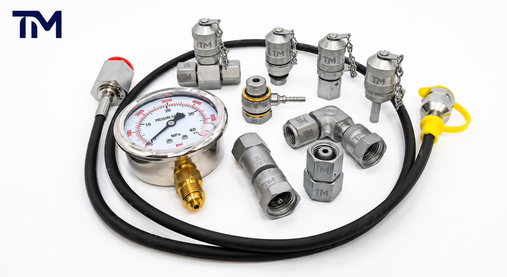
Pressure measurement, fault finding, commissioning, or fluid sampling
The exact gallery, line, or machine point that must represent the signal
Machine port, diagnostic coupling, hose or adapter, and instrument
Normal, transient, connection, and disconnection conditions kept separate
Isolation, stored energy, access, restraint, and site procedure recorded
Verified, unresolved, or assigned for application release
Start with the measurement or sampling task, then map the circuit location, machine access, operating condition, and diagnostic route. The two overviews below help a team identify the right application page before it prepares a release record.
Define the normal system pressure, the expected transient range, the pressure gauge or transducer connection, the test hose length, and the safe connection procedure. Only accept a pressure rating when it belongs to the proposed part and the complete measurement route.
Define the fluid, sample objective, operating state, flushing plan, container interface, and location in the circuit. ISO 4021 says sampling is preferably performed at a sampling point in a main flowline; reservoir sampling is used only when no suitable sampling point is available.
Plan a representative collection location and a clean, controlled route for the sample. Record the sampling objective and the operating state used for collection.
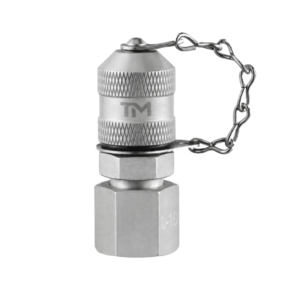
Review diagnostic access where dust, impact, machine guarding, and field cleaning affect the technician’s route. Capture the drill or mining equipment context and the workable connection position.
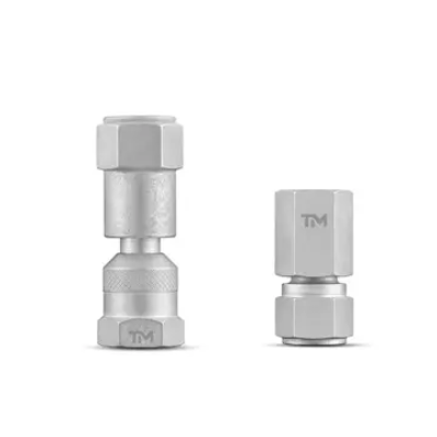
Identify the intended gallery and the hose path around valves, lines, and tool clearances. The application record should distinguish the measured circuit from nearby connections.
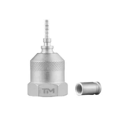
Map the circuit and technician position on the excavator with guards and service access considered. Include vibration, dirt exposure, hose routing, and the machine’s safe working condition.
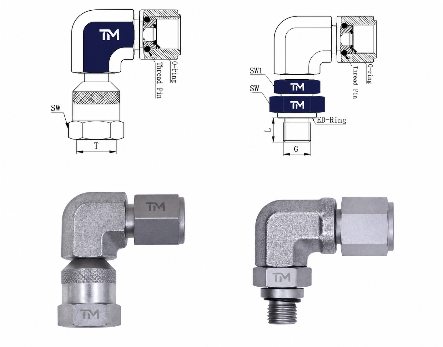
Separate the diagnostic measurement route from lifting and servicing controls. Record the circuit function, technician access, residual-pressure controls, and any support or restraint requirements.
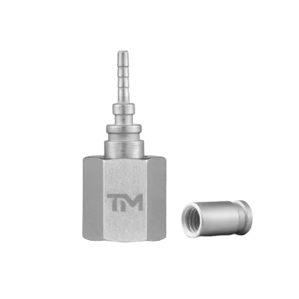
Use one row as an application record and attach the machine reference, location image, or drawing. Each gate keeps the task, interface, access, and release responsibility aligned for the selected child application.
Record the machine-side port, diagnostic interface, machine model, circuit location, and available model evidence. Assign an owner to any missing information before the application route is released.
Interface evidence: name the thread family shown on the drawing, such as JIC or a metric port, and attach the design drawing plus any applicable SAE or ISO reference.
Record application inputs that affect the diagnostic route and the release review. This page does not prescribe product materials or finishes.
State the hydraulic medium, expected temperature range, cleaning method, and sampling or measurement condition. Note any change in fluid or service duty that must be reviewed.
Record dirt, washdown, corrosion exposure, vibration, impact, guarding, and the technician's working position. These inputs determine whether the diagnostic route is practical to use and maintain.
Keep the approved machine model, circuit location, drawing revision, and service procedure with the application record. Recheck the route when the machine configuration or maintenance process changes.

Release the selected application route with the information needed to locate, access, and use the diagnostic point safely. Keep the machine reference, responsibility, and open actions with the application record.
Assign each open item to the equipment owner, application engineer, product engineer, or document controller. A visible owner keeps a missing machine or route fact from being treated as release-ready.
Confirm that the record matches the selected child application, the machine reference, the safe state, and the planned task. Keep unresolved items visible until their responsible owner closes them.
Provide a stamped part number, a drawing, or a clear photograph with a ruler beside it, plus the machine and intended task.
Match the task to fluid sampling, mining and rock drilling, valve blocks, excavators, or cranes.
Record the diagnostic route, machine-side port, task, operating basis, fluid, environment, access, safe state, and release evidence.
Keep the equipment owner, application engineer, product engineer, and document controller aligned on open actions.
Confirm the location, safe state, diagnostic task, and release record before use.
Part number, drawing, or measured reference
Why it changes the answer:Connects the application record to the actual machine
Pressure monitoring, troubleshooting, commissioning, or sampling
Why it changes the answer:Changes the connector, hose, instrument, and operating procedure
Normal operating condition, event to observe, and connection state
Why it changes the answer:Keeps the diagnostic task and safe state specific
Fluid name, temperature band, and cleaning method
Why it changes the answer:Records application constraints for review
Vibration, dirt, washdown, impact, guarding, and access
Why it changes the answer:Shows whether the route is practical for the technician
Machine reference, route, safe state, open items, and owner
Why it changes the answer:Aligns the application release with site responsibility
Defines the diagnostic task, circuit location, guarded condition, access restrictions, and responsible site procedure.
Reviews the signal or sampling route, operating basis, environment, and unresolved application assumptions.
Reviews the available model evidence and interfaces against the documented application inputs.
Preserves the approved revision, responsible owner, and release status with the application record.
Record the task, circuit location, diagnostic and machine-side interfaces, instrument or sampling route, operating basis, fluid, environment, access, safe state, evidence status, and approval owner.
Only when the location, connector, procedure, cleanliness controls, and proposed component are approved for both tasks. ISO 4021 prefers a sampling point in a main flowline and uses reservoir sampling only when no suitable sampling point is available; pressure monitoring follows the intended signal and instrument route.
Identify the permitted operating condition, isolation method, residual-pressure control, support or restraint, guarded access, connection and disconnection sequence, and responsible site procedure. A diagnostic connection does not replace servicing controls for stored hydraulic energy.
Use the fluid-sampling route for representative sample collection, the mining and rock-drilling route for harsh field access, the valve-block route for named galleries, the excavator route for mobile service access, or the crane route for lifting-equipment diagnostic conditions.
Review it when the machine model, circuit location, operating condition, fluid, access arrangement, or site procedure changes. Keep the release owner and open actions with the updated record.
